A practical technical guide for mining, motors, fans, pumps, conveyors, and harsh-duty grease points
By Khash
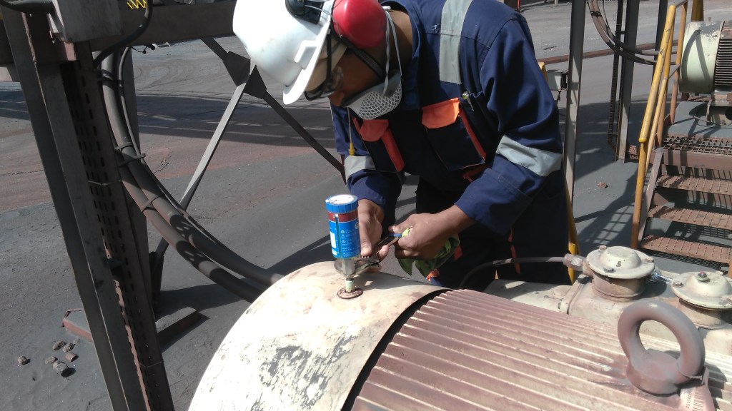
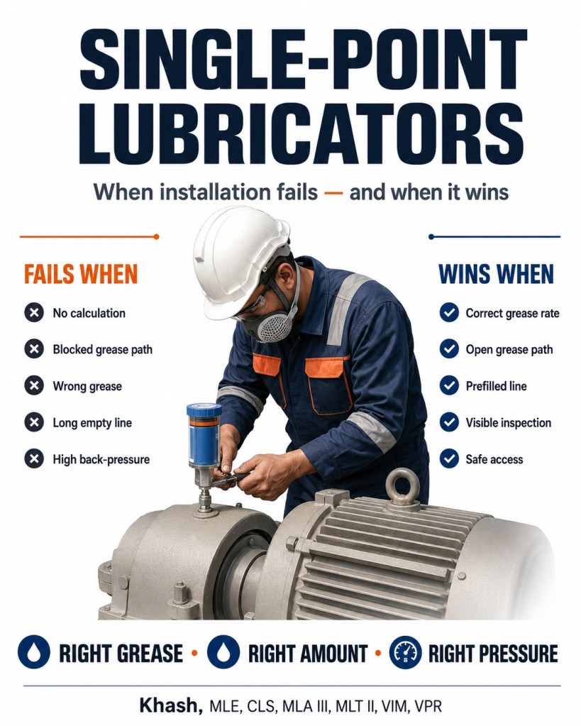
In some of my above photos, the technician is installing a single-point lubricator directly on a motor or driven-equipment bearing housing in a dusty mining-type environment. That is exactly the kind of application where single-point lubricators can be excellent — but only when the lubrication point, grease, pressure, temperature, vibration, feed line, and inspection method are correctly engineered.
A single-point lubricator does not fix a bad lubrication program by itself. It only works when the bearing can accept the grease at the required rate and pressure.
The simplest rule is:
A single-point lubricator wins when it delivers the right grease, in the right amount, at the right pressure, through a clean and open path, at the correct interval. It fails when it is installed like a smart grease nipple without calculation or verification.
1. What a single-point lubricator actually does
A single-point lubricator, or SPL, is a small automatic lubrication device that supplies one lubrication point with grease or oil over a selected period. It may be gas-driven, electrochemical, spring-driven, or electromechanical.
Its job is to replace the old manual routine of “come once a week or once a month and pump grease.” Instead, the SPL provides small, repeated grease delivery over time.
This can reduce under-lubrication, reduce overgreasing, improve safety, and keep bearings lubricated while the machine is operating. Manufacturer literature lists typical SPL applications such as bearing housings, electric motors, fans, pumps, conveyors, cranes, and hazardous or restricted-access locations.
But there is a technical trap:
The SPL is not the lubrication strategy. It is only the delivery device.
The strategy must still define:
- correct grease,
- correct quantity,
- correct dispense rate,
- correct pressure capability,
- direct or remote mounting,
- pipe or hose diameter,
- purge method,
- inspection frequency,
- replacement date,
- failure-response action.
2. When single-point lubricator installation fails
Failure mode 1: No lubrication calculation
The most common failure is selecting the lubricator setting by habit.
Examples:
- “Set everything to 3 months.”
- “Use the biggest cartridge.”
- “Install one on every bearing.”
- “If the bearing is hot, increase the setting.”
- “If grease is not coming out, use a shorter setting.”
This is not lubrication engineering.
The required grease amount depends on:
G = f(D, B, n, T, L, C, K)
Where:
| Symbol | Meaning |
|---|---|
| (D) | bearing outside diameter |
| (B) | bearing width |
| (n) | running speed |
| (T) | operating temperature |
| (L) | load condition |
| (C) | contamination level |
| (K) | correction factors for orientation, vibration, sealing, purge need |
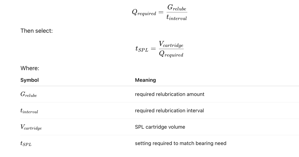
The lubricator output is:
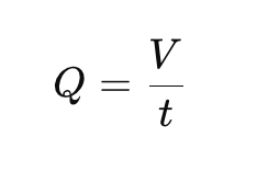
Where:
| Symbol | Meaning |
|---|---|
| (Q) | grease delivery rate |
| (V) | cartridge volume |
| (t) | selected discharge period |
If the bearing needs 0.8 ml/day and the lubricator is set to deliver 0.25 ml/day, the installation looks successful but the bearing is starving. If the bearing needs 0.2 ml/day and the lubricator delivers 1.0 ml/day, the bearing may overheat, churn grease, damage seals, or purge grease into the motor or housing.
SKF specifically notes that lubrication-interval calculations should account for operating conditions and selected grease properties to minimize under- or over-lubrication and optimize grease consumption.
Failure mode 2: The grease path is not open
Before installing an SPL, the lubrication point must be checked. A blocked grease path defeats the whole installation.
Common blocked-path causes:
- hardened old grease,
- dried soap thickener,
- contaminated grease passage,
- plugged grease nipple,
- collapsed grease line,
- wrong fitting,
- bearing shield or seal blocking flow,
- no relief path,
- old grease incompatible with new grease,
- bearing already damaged and overheated.
A single-point lubricator cannot reliably push grease through a blocked bearing housing. Installation guides for automatic lubricators specifically instruct technicians to check counter-pressure before installation; one guide notes that many bearing points require about 0.5 to 2 bar without extension tubes or hoses, and if system pressure exceeds 2 bar, the lube point should be purged with a mechanical grease gun. (perma-tec.com)
Practical rule:
If a grease gun cannot purge the point smoothly, do not expect a low-pressure single-point lubricator to succeed.
Failure mode 3: The feed line is too long or too small
Grease is not oil. It has high flow resistance, especially at low temperature, through small-bore tubing, long lines, elbows, and fittings.
The line pressure increases with:
- longer line,
- smaller internal diameter,
- cold grease,
- high NLGI grade,
- high base-oil viscosity,
- many elbows,
- clogged fittings,
- high bearing back-pressure.
A useful engineering approximation is:

The lubricator must generate more pressure than the total system resistance.
Manufacturer application guidance gives a practical rule of thumb for tube pressure loss: approximately 1 bar per metrefor 9.5 mm internal-diameter tube and 1.5 bar per metre for 6 mm internal-diameter tube under stated reference conditions. It also states that maximum grease-line length depends on the lubrication system, lubricant, and operating temperature. (perma.com.au)
This is where many installations fail. A technician installs the lubricator remotely with a long small tube, but the SPL cannot overcome the pressure resistance. The lubricator appears to be working, but little or no grease reaches the bearing.
Failure mode 4: The line is not prefilled
This is a very serious field problem.
If a remote-mounted SPL is connected to an empty grease line, the lubricator must first fill the line before any grease reaches the bearing.
Example:
- Tube internal diameter: 6 mm
- Tube length: 2 m
- Tube volume:
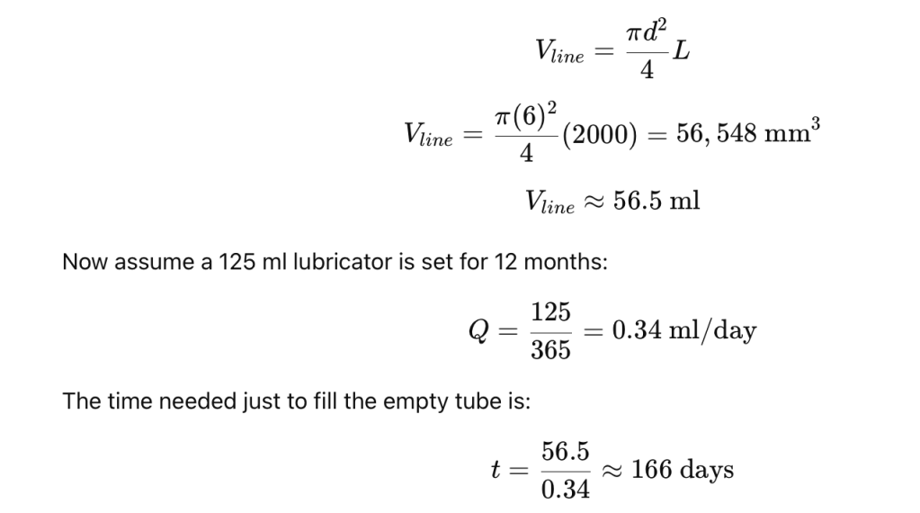
That means the bearing may receive no grease for more than five months.
This is why remote lines must be prefilled with the same lubricant before startup. Perma’s installation guidance specifically instructs technicians to prefill lubrication points and grease lines, and to use the same lubricant for prefilling and the lubricator cartridge. (perma-tec.com)
Practical rule:
An empty remote line can turn a good SPL into a delayed-failure device.
Failure mode 5: Wrong lubricator pressure capability
Not all single-point lubricators are equal.
Some gas-driven units are low-pressure devices. Some electromechanical units can generate higher pressure. Multi-point pump systems may generate much higher pressure.
For example, one gas-driven single-point lubricator family lists a maximum operating pressure of 5 bar and a maximum grease feed-line length of 300 mm, while another electromechanical single-point type lists higher pressure capability and longer possible feed-line length, dependent on grease, temperature, and application back-pressure.
This matters in mining, cement, quarrying, and outdoor motor applications because grease paths are often dirty, long, cold at night, hot in the day, and exposed to vibration.
Practical rule:
Low-pressure SPLs should normally be direct-mounted or used with very short feed lines. Remote installations need pressure verification.
Failure mode 6: Direct mounting on severe vibration
Direct mounting is simple, but it is not always correct.
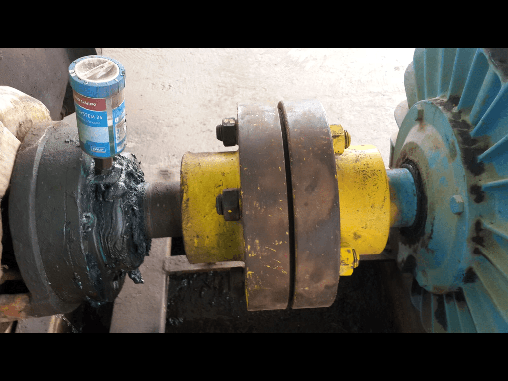
In your photo, the SPL appears to be installed directly on the housing. That may be acceptable if vibration is low and the fitting is protected. But on vibrating equipment, direct-mounted lubricators can fail mechanically.
Possible failures:
- cracked fitting,
- broken reducer,
- loose adapter,
- leaking thread,
- damaged lubricator body,
- loosened cartridge,
- dirt entry through loose connection,
- false assumption that grease is entering the bearing.
For high-vibration locations, remote mounting with a bracket is often better. The lubricator should be mounted on a stable structure, connected with a short prefilled line, and protected from impact. Manufacturer literature identifies vibration, limited space, hazardous environments, and remote mounting requirements as reasons to choose an appropriate electromechanical lubricator or accessory arrangement.
Practical rule:
If the machine shakes, do not hang a lubricator from a small threaded adapter unless the vibration level and fitting strength have been considered.
Failure mode 7: Temperature is ignored
Temperature affects both the lubricator and the grease.
High temperature can:
- accelerate discharge in some gas-driven designs,
- soften grease,
- reduce base-oil viscosity,
- shorten grease life,
- damage seals,
- oxidize grease,
- increase purge rate.
Low temperature can:
- slow gas-driven output,
- increase grease stiffness,
- increase line pressure,
- stop grease flow,
- delay startup discharge.
This is why constant output at variable temperature may require an electromechanical unit rather than a simple gas-driven device. SKF describes electromechanical single-point lubricators as preferred when application conditions include variable temperatures, vibration, limited space, or hazardous environments requiring remote mounting.
Practical rule:
A lubricator setting made at 25 °C may not deliver the same practical result at 5 °C or 60 °C.
Failure mode 8: The wrong grease is installed
Single-point lubricators fail when the grease is wrong for the bearing, the old grease, the seals, the temperature, or the pumping distance.
Wrong grease can cause:
- soap thickener incompatibility,
- oil separation,
- hardening,
- softening,
- blocked lines,
- poor pumpability,
- poor water resistance,
- inadequate EP protection,
- seal swelling,
- loss of film strength.
The risk is higher when the bearing was previously lubricated with an unknown grease. If the old grease is lithium complex and the new grease is calcium sulfonate, polyurea, bentone, aluminium complex, or another thickener type, compatibility must be checked before conversion.
The safest conversion is:
- Identify old grease.
- Identify new grease.
- Check compatibility.
- Purge old grease where practical.
- Use the same grease in the lubricator, line, and bearing feed path.
- Monitor temperature and vibration after changeover.
Manufacturer instructions for SPL installation emphasize using the same lubricant for prefilling and the lubricator cartridge. (perma-tec.com)
Failure mode 9: No purge route
A bearing must be able to accept grease and relieve excess grease.
If there is no purge path, pressure builds. The result may be:
- seal damage,
- grease churning,
- bearing overheating,
- grease entering motor windings,
- grease leaking through unwanted paths,
- lubricant trapped in housing cavity,
- SPL unable to discharge.
This is especially important for electric motors. Too much grease can damage seals, contaminate windings, or increase temperature. SPLs can reduce manual overgreasing, but only if the calculated quantity and purge route are correct.
Practical rule:
A bearing without a controlled purge path can be under-lubricated and over-pressurized at the same time.
Failure mode 10: The SPL is installed on the wrong point
Not every grease nipple feeds the bearing.
Some nipples feed:
- housing cavity,
- labyrinth seal,
- purge cavity,
- external seal,
- shaft seal,
- wrong side of the bearing,
- old blocked passage,
- decorative or abandoned fitting.
A technician may remove a grease nipple and install an SPL, assuming the point feeds the bearing. In reality, the grease may be going into a dead cavity.
Before installation, verify:
- grease path drawing,
- housing section,
- old grease purge location,
- bearing type,
- seal arrangement,
- grease relief point,
- flow path from nipple to bearing.
Practical rule:
Never install an SPL just because a grease nipple exists. Confirm where the grease actually goes.
3. When single-point lubricators win
Win condition 1: The point is hazardous or difficult to reach
This is one of the strongest reasons to use SPLs.
Manual greasing often requires:
- climbing,
- removing guards,
- reaching near rotating equipment,
- opening panels,
- standing near hot surfaces,
- working in dusty or wet areas,
- greasing while production is waiting.
A properly installed SPL reduces the need for frequent manual access. SKF notes that automatic lubrication allows workers to focus on inspection and other value-added tasks, and its literature lists applications in restrictive and hazardous locations.
For the type of mining environment shown in your photo, this is a real advantage.
Win condition 2: Small, continuous grease supply is better than large manual shots
Manual greasing often creates this pattern:
- Bearing receives too much grease immediately after greasing.
- Temperature rises due to churning.
- Excess grease purges or remains trapped.
- Bearing slowly runs down toward starvation.
- Technician returns and repeats the cycle.
A single-point lubricator can provide a steadier feed:
[
\text{Small dose} + \text{regular interval} = \text{more stable grease film}
]
This is especially useful for:
- electric motor bearings,
- fan bearings,
- pump bearings,
- conveyor pulley bearings,
- small plummer-block bearings,
- bearings in dusty locations,
- slow-to-moderate speed grease-lubricated points.
Win condition 3: The bearing needs contamination purging
In dirty environments, grease does two jobs:
- Lubricates the rolling contact.
- Helps block contamination entry.
A small continuous grease feed can maintain slight outward purge at seals and labyrinths, helping keep dust and water out.
This is valuable in:
- mining conveyors,
- cement plants,
- quarry crushers,
- outdoor fans,
- coal handling,
- dusty motors,
- material handling equipment.
But the purge rate must be controlled. Too little grease does not protect the seal. Too much grease overheats the bearing or wastes lubricant.
Win condition 4: The lubrication point has known low back-pressure
SPLs work well when the grease path is short, clean, and open.
Ideal conditions:
- direct mounting or very short prefilled line,
- clean bearing housing,
- known purge path,
- correct grease,
- stable temperature,
- moderate bearing speed,
- moderate vibration,
- proper mounting bracket if remote,
- visible inspection access,
- calculated output rate.
In these cases, SPLs can improve reliability dramatically because they eliminate missed routes, inconsistent technician habits, and overgreasing events.
Win condition 5: The unit is visible and inspectable
An SPL should not be hidden and forgotten.
The installation wins when technicians can easily check:
- cartridge emptying rate,
- installation date,
- exchange date,
- discharge setting,
- grease type,
- blockage indicator,
- LED status if fitted,
- leakage,
- damaged fittings,
- loose tubing,
- contamination around the point.
Some SPLs use transparent containers for visual inspection of dispense rate, and some electromechanical units include LED indicators or alarm functions.
Practical rule:
If nobody can see it, nobody will know it failed.
Win condition 6: Remote mounting is engineered correctly
Remote mounting wins when it is used for the right reasons:
- high vibration at bearing housing,
- hot bearing housing,
- unsafe access,
- moving guards,
- restricted space,
- impact risk,
- washdown exposure,
- need for visual inspection.
Correct remote installation requires:
- short line,
- large enough internal diameter,
- prefilled line,
- same grease in line and lubricator,
- low-pressure path,
- proper bracket,
- protection from mechanical damage,
- pressure test before startup.
Incorrect remote mounting fails when the line is long, empty, cold, unprotected, and too small.
4. Technical installation standard
A strong SPL installation standard should follow this sequence.
Step 1: Identify the asset and lubrication point
Record:
- equipment number,
- bearing type,
- bearing size,
- speed,
- operating temperature,
- load condition,
- orientation,
- contamination level,
- grease type,
- current manual quantity,
- current manual frequency,
- failure history.
Do not install SPLs only because the asset has a grease nipple.
Step 2: Calculate required grease delivery
Determine required grease per day or per month.
Then correct for:
- temperature,
- contamination,
- bearing speed,
- bearing size,
- grease type,
- purge requirement,
- duty cycle,
- intermittent operation.
If the machine only runs 8 hours/day but the lubricator discharges continuously, the bearing may receive grease during shutdown. For intermittent operation, a machine-controlled electromechanical lubricator may be better. SKF literature describes a cabled drive unit option that can lubricate only when equipment is running and can connect to machine control.
Step 3: Verify back-pressure
Before installing:
- Remove grease nipple.
- Fit pressure test adapter.
- Pump grease slowly.
- Observe required pressure.
- Confirm grease reaches the correct purge point.
- Purge old grease.
- Record pressure.
Do not guess.
If pressure is high, identify why:
- blocked passage,
- hardened grease,
- line too long,
- wrong grease,
- no purge path,
- wrong port,
- bearing seal blockage,
- temperature too low.
Installation instructions from a major SPL manufacturer explicitly require counter-pressure checking before installation and recommend purging if pressure is excessive. (perma-tec.com)
Step 4: Select direct or remote mounting
Direct mounting is best when:
- vibration is low,
- temperature is acceptable,
- space is available,
- SPL is protected,
- technician can inspect it,
- line length can be zero,
- contamination risk at fitting is low.
Remote mounting is best when:
- vibration is high,
- housing is hot,
- bearing point is unsafe,
- access is poor,
- SPL may be hit or broken,
- guard removal is needed,
- inspection must be done from safe location.
The decision should not be based on convenience only. It should be based on vibration, pressure, temperature, access, and safety.
Step 5: Prefill the system
Before activation:
- purge the bearing with correct grease,
- prefill all tubing,
- prefill adapters,
- remove air pockets,
- use same grease as lubricator,
- confirm purge path.
No empty lines. No unknown grease. No trapped air.
Step 6: Install with mechanical protection
Good installation practice:
- use correct thread adapter,
- avoid excessive reducer stacks,
- use sealant carefully,
- do not block the port,
- use bracket for remote mount,
- protect tube from abrasion,
- avoid tight bends,
- avoid low points where water collects,
- avoid heat sources,
- avoid standing on or leaning against lubricator,
- tag the unit.
Bad installation:
- long unsupported lubricator on a vibrating motor,
- tiny tube with many elbows,
- no bracket,
- unknown grease,
- no purge,
- no pressure test,
- no date tag,
- no route inspection.
Step 7: Commission and verify
After installation, check:
- correct setting,
- activation completed,
- cartridge begins moving,
- no leakage,
- no broken fitting,
- no abnormal bearing temperature,
- no grease pressure issue,
- grease purge visible where expected,
- vibration stable,
- ultrasound condition stable.
Within the first inspection interval, verify that the cartridge is discharging at the expected rate. A transparent reservoir can help visually confirm dispense rate.
5. Direct-mounted SPL: pass/fail checklist for the photo-type installation
For a motor or bearing housing like the one in your image, I would use this checklist.
Direct installation can pass if:
- bearing point was pressure-tested,
- old grease was purged,
- same grease is used,
- lubricator is within temperature limit,
- vibration is low enough,
- unit is not exposed to impact,
- fitting is short and strong,
- purge path is known,
- setting is calculated,
- technician can see the unit,
- installation and exchange dates are marked.
Direct installation should be rejected if:
- housing vibration is high,
- fitting stack is long and weak,
- motor surface is too hot,
- cartridge is exposed to impact,
- dust can pack around fitting,
- SPL blocks access or guard,
- bearing point has high back-pressure,
- point has unknown grease,
- purge path is blocked,
- the lubricator cannot be inspected.
In many mining plants, the better solution is often:
Remote-mounted SPL on a rigid bracket + short prefilled line + pressure test + correct grease + visible tag.
6. Single-point lubricator selection logic
Gas-driven SPL
Best for:
- simple points,
- short or direct installation,
- low back-pressure,
- stable temperature,
- non-critical points,
- low to moderate grease demand.
Weaknesses:
- temperature sensitivity,
- limited pressure,
- poor for long lines,
- poor for high resistance,
- less precise output.
Electromechanical SPL
Best for:
- variable temperature,
- higher pressure requirement,
- remote mounting,
- vibration-prone applications,
- critical points,
- need for status indication,
- higher grease consumption.
Weaknesses:
- battery/power dependence,
- higher cost,
- still requires pressure/path verification.
Multi-point automatic lubrication system
Better than SPL when:
- many points are close together,
- points need synchronized delivery,
- inspection must be centralized,
- high pressure is required,
- alarms are required,
- lines are longer,
- one reservoir should feed many bearings.
SKF describes multi-point automatic lubrication systems for multiple lubrication points, with monitoring functions such as low-level and malfunction alarms, and higher-pressure pump capability compared with simple single-point units.
7. Common failure symptoms after installation
| Symptom | Likely cause |
|---|---|
| Cartridge does not empty | not activated, high back-pressure, cold grease, blocked line |
| Cartridge empties but bearing is dry | empty line not prefilled, wrong port, leakage before bearing |
| Bearing temperature rises | overgreasing, wrong grease, no purge path, excessive churning |
| Grease leaks at adapter | high pressure, bad thread, blocked bearing path |
| SPL body cracks | vibration, impact, unsupported direct mounting |
| Bearing fails soon after installation | bearing already damaged, blocked line, wrong grease, no calculation |
| Grease hardens in line | incompatible grease, heat, oxidation, low flow |
| Contamination enters around fitting | poor adapter sealing, no cap/protection, washdown/dust |
| Bearing gets noisy | starvation, contamination, wrong grease, overgrease heat, existing damage |
8. When SPLs should not be used
Do not use single-point lubricators blindly on:
- very high-speed motor bearings with tight grease-volume limits,
- bearings requiring very small precision grease amounts unless calculation is accurate,
- points with unknown grease path,
- blocked lubrication passages,
- very high back-pressure points,
- long remote lines with low-pressure devices,
- sealed-for-life bearings,
- oil-lubricated bearings,
- points needing large purge volumes,
- bearings already in distress,
- applications needing centralized alarmed lubrication,
- extreme heat beyond lubricator or grease rating,
- high vibration without remote bracket.
In these cases, use manual precision greasing, a centralized lubrication system, redesign of the grease path, or bearing/housing correction before automation.
9. Why SPLs sometimes get blamed unfairly
Many SPL “failures” are not lubricator failures. They are installation and program failures.
The SPL gets blamed when the real root cause is:
- blocked grease path,
- wrong grease,
- no pressure test,
- wrong output setting,
- empty feed line,
- old bearing damage,
- no purge path,
- excessive temperature,
- vibration damage,
- poor inspection,
- wrong mounting location.
The lubricator did not fail. The installation failed.
10. Strong technical report wording
You can use this wording in a maintenance or RCA report:
The single-point lubricator installation should be evaluated as a complete lubrication delivery system, not as an isolated cartridge. Correct operation depends on calculated lubricant demand, lubricant compatibility, verified grease path, acceptable counter-pressure, prefilled feed lines, correct mounting method, suitable temperature range, and routine inspection. Failure of an SPL installation commonly results from blocked grease passages, excessive line resistance, empty remote tubes, wrong grease, over- or under-lubrication settings, vibration-damaged fittings, or installation on an unsuitable lubrication point. Where the point is accessible only under unsafe conditions, or where frequent small grease delivery improves contamination purging and lubrication stability, a correctly engineered SPL can significantly improve reliability.
11. Practical field standard
A strong plant rule would be:
No single-point lubricator shall be installed until the lubrication point is identified, pressure-tested, purged, calculated, tagged, and assigned an inspection route. Remote lines shall be prefilled with the same grease, kept as short as practical, protected from damage, and verified for flow before release to operation.
12. Main takeaway
Single-point lubricators win when they are used as precision automatic lubrication devices.
They fail when they are used as automatic grease nipples.
For mining and heavy industry, the winning formula is:
calculated grease rate + compatible grease + open grease path + pressure test + prefilled line + correct mounting + visible inspection + documented replacement date.
Khash
MLE, CLS, MLA III, MLT II, VIM, VPR
