Fluting on the Shaft and Bearing Inner Ring: Electrical Damage Is Not Limited to the Raceway
By Khashayar Hajiahmad, MLE, CLS, MLA III, MLT II, VIM, VPR Pro
When most people hear the word fluting, they immediately think of the classic washboard pattern found on a bearing raceway, especially in electric motors controlled by variable frequency drives. In many failure investigations, the outer raceway or inner raceway is inspected first, and once electrical fluting is identified there, the investigation often stops.
That is a mistake.
Electrical discharge damage does not only occur on the bearing raceway. It can also occur on the shaft, the bearing inner ring bore, the inner ring seating surface, the shoulder contact area, the locknut face, the coupling fit, and any metallic interface that becomes part of the current path.
The photos shown are a very good field example of why a complete bearing failure analysis must include not only the rolling contact surfaces, but also the shaft journal and the inner ring bore. In many cases, the shaft and the bearing inner ring can show evidence of electrical erosion, frosting, pitting, or fluting-like patterns before the damage becomes obvious on the raceway.
1. What Is Fluting?
Fluting is a form of surface damage caused by repeated electrical discharge through a rolling bearing or a metallic contact interface.
In simple terms, the machine develops an electrical potential difference between two components. When the voltage becomes high enough to break through the lubricant film or microscopic air gap, a small electrical arc occurs. This arc removes a tiny amount of material from the surface. When this process repeats thousands or millions of times, it creates visible damage.
Depending on severity, the damage may appear as:
- Frosting
- Gray discoloration
- Electrical pitting
- Micro-craters
- Washboard patterns
- Axial or circumferential lines
- Burn marks
- Blackened grease
- Localized polishing
- Surface roughness
- Inner ring bore damage
- Shaft journal marking
In bearings, this is often called:
- Electrical erosion
- EDM damage
- Electrical pitting
- Bearing current damage
- Electrical discharge machining effect
- Fluting
Although the term “fluting” is often used for the regular washboard pattern on raceways, the same electrical discharge mechanism can damage other parts of the bearing assembly.
2. Why Fluting Is Commonly Associated with Bearings
Bearings are vulnerable because they contain multiple conductive components separated by very thin lubricant films.
A bearing has:
- Inner ring
- Outer ring
- Rolling elements
- Cage
- Lubricant film
- Shaft contact
- Housing contact
When current passes through a bearing, the rolling element contacts become natural discharge points. This happens because the lubricant film between the rolling element and raceway can act like a dielectric layer.
At low voltage, the lubricant film separates the surfaces.
At higher voltage, the film breaks down.
Once breakdown occurs, the current discharges through the contact zone. The discharge creates a microscopic crater. Repeated discharges produce a frosted surface. If the machine continues operating, the damage can progress into regular fluting patterns.
This is why electrical damage is often seen on raceways and rolling elements.
However, the bearing is not the only possible discharge point.
3. Why the Shaft Can Also Develop Fluting or Electrical Marking
A shaft is usually assumed to be only a conductor carrying the current toward the bearing. But the shaft itself can become a damaged component when current transfers between the shaft and another surface.
The most important area is the shaft-to-inner-ring fit.
The bearing inner ring is mounted on the shaft. Ideally, this contact is mechanically tight and electrically stable. However, in real machines, the interface may contain:
- Microscopic gaps
- Surface asperities
- Oxide films
- Fretting debris
- Lubricant residue
- Contamination
- Imperfect seating
- Small movement under load
- Slight looseness due to fit degradation
- Thermal expansion differences
These small discontinuities can create localized electrical resistance. When shaft voltage exists, the current may arc across these microscopic gaps. The result is electrical damage on the shaft journal and inner ring bore.
This is very important:
The current does not know that the raceway is the “expected” failure location. It simply follows the available electrical path. Any contact interface in that path can be damaged.
4. Electrical Current Path Through the Bearing Assembly
In many rotating machines, especially VFD-driven motors, the current path may look like this:
VFD
→ Motor frame and stator
→ Rotor
→ Shaft
→ Bearing inner ring
→ Rolling elements
→ Bearing outer ring
→ Housing
→ Ground
But in practice, the path is often more complex.
Current can also travel through:
Shaft
→ Inner ring bore
→ Inner ring side face
→ Locknut or sleeve
→ Bearing shoulder
→ Housing
→ Ground
Or:
Shaft
→ Coupling hub
→ Driven machine shaft
→ Driven machine bearing
→ Ground
Or:
Shaft
→ Seal contact
→ Seal housing
→ Ground
Or:
Shaft
→ Inner ring fit interface
→ Bearing ring
→ Housing
Because of these possible paths, fluting-like electrical damage can appear in areas that are often ignored during inspection.
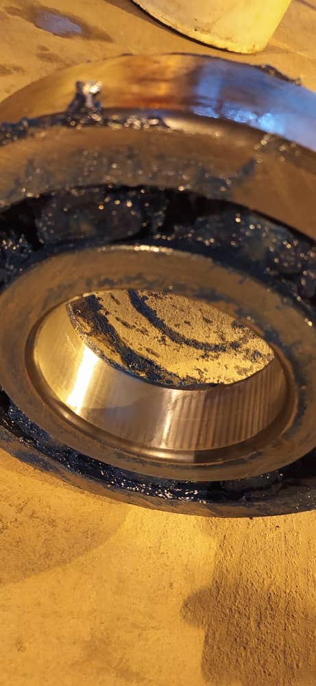
5. What the Photos Suggest
From the images, several features are worth noting.
The bearing shows signs of severe distress. There is dark grease, smearing, surface distress, and visible damage on the rolling elements and bearing race areas. The condition of the cage and lubricant also suggests the bearing has been exposed to abnormal operating conditions.
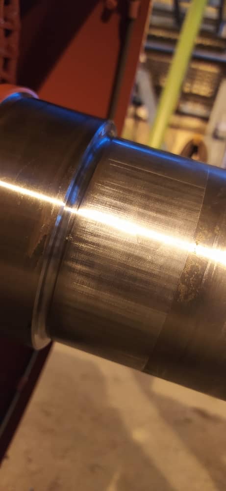
The shaft journal image shows circumferential banding and surface marking. These marks should not be dismissed as simple machining marks or normal wear without further inspection. When a shaft shows repeated banding, dull gray areas, and fine surface texture changes near the bearing seating area, electrical damage should be considered as a possible contributor.
The inner ring and bore area should also be carefully inspected. Damage at the bore can confirm whether current passed through the shaft-to-inner-ring interface.
Possible observations from this type of failure include:
- Electrical frosting on the shaft seating area
- Micro-pitting on the shaft journal
- Burnishing at the bearing fit
- Black oxide deposits
- Fretting corrosion mixed with electrical erosion
- Inner ring bore discoloration
- Fine axial or circumferential marks
- Localized overheating
- Evidence of ring creep
- Grease carbonization
- Darkened lubricant due to electrical activity and heat
The key point is that the shaft surface must be treated as part of the evidence, not just as a mounting location.
6. Difference Between Race Fluting and Shaft Fluting
Raceway fluting is usually caused by repeated current discharge through the rolling contact zone. It often creates a regular washboard pattern across the raceway.
Shaft fluting or shaft electrical marking is different. It may not always show a perfect washboard pattern. It can appear as:
- Circumferential bands
- Dull gray surface patches
- Fine pitting
- Burn marks
- Surface roughness
- Electrical frosting
- Dark staining
- Repeated arc marks around the journal
- Uneven polished areas
Because the shaft-to-inner-ring interface is not a rolling contact, the damage pattern can look different from classic raceway fluting. This is one reason it is often misdiagnosed.
A technician may look at the shaft and say:
“This is just fretting.”
Or:
“This is only a poor fit.”
Or:
“This is from installation.”
Those explanations may be partly correct, but they may not be the full root cause. In many cases, mechanical fit problems and electrical discharge work together.
7. The Combination of Electrical Discharge and Fretting
One of the most dangerous combinations is electrical discharge plus fretting.
Fretting occurs when two contact surfaces experience very small relative movement. In a bearing fit, this can happen if the interference fit is insufficient, if the loading direction is unfavorable, if vibration is high, or if the shaft and inner ring are not seated correctly.
Fretting produces oxide debris and damages the surface. Electrical discharge then attacks the damaged area more easily. The discharge creates craters and changes the surface condition. The damaged surface then becomes more prone to movement and fretting.
This creates a destructive cycle:
Minor looseness
→ Micro-movement
→ Fretting
→ Oxide formation
→ Higher contact resistance
→ Electrical arcing
→ Surface pitting
→ More looseness
→ More fretting
→ Faster failure
For this reason, a shaft with both fretting marks and electrical marks should be taken very seriously.
The root cause may not be only mechanical. It may be mechanical and electrical at the same time.
8. Why the Inner Ring Bore Must Be Inspected
Many bearing failure analyses focus on the raceways, rolling elements, and cage. The inner ring bore is often ignored.
This is a major error.
The inner ring bore is the direct interface between the bearing and the shaft. If current passes from the shaft into the bearing, the bore may show evidence of the current path.
Damage on the inner ring bore may include:
- Arc marks
- Frosted appearance
- Pitting
- Dark staining
- Circumferential scoring
- Localized burn marks
- Material transfer
- Polished patches
- Oxide deposits
- Evidence of ring creep
- Loss of original bore finish
If the bore shows electrical pitting and the shaft journal shows similar marks, it becomes strong evidence that the current did not only pass through the rolling elements. It also passed through the shaft-to-bore interface.
That means the actual failure mechanism is broader than ordinary bearing fluting.
9. How Electrical Damage Progresses
Electrical bearing and shaft damage usually progresses through stages.
Stage 1: Shaft Voltage Development
Voltage develops on the rotor or shaft. This may be caused by VFD common mode voltage, circulating currents, static charge, poor grounding, welding current, or other electrical imbalance.
At this stage, no visible damage may be present.
Stage 2: Lubricant Film Breakdown
The lubricant film acts as an insulating layer until voltage exceeds its dielectric strength. Then a discharge occurs.
The first damage may be microscopic and invisible to the naked eye.
Stage 3: Electrical Frosting
Repeated micro-arcing produces a matte gray appearance on the surface.
This may appear on:
- Raceways
- Rolling elements
- Shaft journal
- Inner ring bore
Stage 4: Pitting and Cratering
As the discharge continues, microscopic craters accumulate. The surface becomes rougher and more reactive.
Lubricant degradation accelerates because metal particles, heat, and oxidation products contaminate the grease or oil.
Stage 5: Fluting Pattern Formation
On rolling surfaces, vibration and repeated rolling contact can organize the damage into a washboard pattern. On shaft surfaces and bores, the pattern may appear as circumferential bands or irregular electrical marking.
Stage 6: Secondary Mechanical Failure
After electrical damage weakens the surfaces, mechanical damage accelerates.
This may include:
- Smearing
- Spalling
- Cage wear
- Rolling element damage
- Heat generation
- Loss of fit
- Bearing creep
- Shaft wear
- Lubricant carbonization
- Catastrophic bearing failure
By the time the bearing is removed, the final appearance may be a combination of electrical, thermal, lubrication, and mechanical damage.
10. Sources of Electrical Current That Can Cause This Damage
Variable Frequency Drives
VFDs are one of the most common sources of electrical bearing damage. Pulse width modulation switching can create common mode voltage. This voltage can induce shaft voltage and bearing currents.
Risk increases when:
- Cable runs are long
- Grounding is poor
- Cable shielding is incorrect
- Switching frequency is high
- Motor insulation is not suitable
- The motor is not designed for inverter duty
- Shaft grounding is missing
- Only one side of the machine is protected
- The driven equipment has a lower impedance path to ground
Circulating Currents
In larger motors, circulating currents can develop due to magnetic asymmetry. These currents may circulate through the shaft, bearings, frame, and housing.
Circulating current damage can affect both drive-end and non-drive-end bearings depending on the machine design and grounding path.
Static Electricity
Static charge can build up in applications involving belts, paper, film, textile, fans, blowers, or high-speed process equipment.
This charge can discharge through bearings and shaft interfaces.
Welding Current
Improper welding practices can destroy bearings very quickly.
If the welding ground clamp is not positioned correctly, current may pass through the shaft and bearings. The result can be severe arcing, pitting, and early bearing failure.
A bearing can be damaged even if the machine is not running during welding.
Poor Grounding
Poor grounding increases the chance that current will find an unintended path.
This may include:
- Bearing contacts
- Shaft fits
- Couplings
- Seals
- Gearbox bearings
- Pump bearings
- Machine frame interfaces
Coupling and Driven Equipment Effects
Sometimes the motor bearing is not the only component at risk. The current may pass through the coupling into the driven machine.
This can damage:
- Pump bearings
- Gearbox bearings
- Fan bearings
- Compressor bearings
- Coupling hubs
- Shaft journals
- Seals
A complete inspection must include the driven equipment when electrical damage is suspected.
11. Why Shaft Grounding Alone May Not Always Be Enough
Shaft grounding rings or brushes are widely used and can be very effective. They provide a lower-resistance path for shaft current to discharge safely.
However, they must be correctly selected, installed, and maintained.
Common problems include:
- Poor contact with the shaft
- Contaminated grounding fibers
- Paint or coating under the mounting surface
- Incorrect installation location
- High shaft runout
- Oil or grease contamination
- Shaft surface oxidation
- Lack of maintenance
- Grounding ring installed on only one side when the current path requires more protection
- Insulated bearing installed without understanding the full circuit
If the shaft grounding system does not provide the lowest impedance path, current may still pass through the bearing or the shaft-to-inner-ring fit.
This is why the entire electrical circuit must be evaluated.
12. Insulated Bearings and Hybrid Bearings
There are several common strategies to reduce electrical bearing damage.
Insulated Bearings
Insulated bearings have a coating, usually on the outer ring or inner ring, to interrupt current flow through the bearing.
They are often installed on the non-drive end of electric motors.
However, insulated bearings do not eliminate shaft voltage. They only block one possible path. If another path exists through the driven machine, coupling, or opposite bearing, damage may still occur elsewhere.
Hybrid Ceramic Bearings
Hybrid bearings use ceramic rolling elements. Ceramic rolling elements are electrically insulating, which reduces the risk of current passing through the rolling contacts.
They are useful in many VFD motor applications, but they must be applied correctly. They do not automatically solve every grounding issue in the machine train.
Shaft Grounding Devices
Grounding rings, brushes, or grounding straps provide a controlled path for current.
They are often used together with insulated bearings.
Common Mode Filters
Filters can reduce common mode voltage generated by the VFD. This attacks the problem at the electrical source rather than only protecting the bearing.
Proper Cable Shielding and Grounding
Correct VFD cable selection and shield termination are critical. Poor shielding or poor grounding can increase shaft voltage and bearing current risk.
13. Inspection Procedure After Suspected Electrical Bearing Damage
A proper failure analysis should follow a structured process.
Step 1: Document the Bearing Condition Before Cleaning
Before cleaning the bearing, inspect and photograph:
- Grease condition
- Color of lubricant
- Metal debris
- Carbonized deposits
- Cage condition
- Rolling element condition
- Raceway appearance
- Seal condition
- Heat discoloration
Do not immediately wipe away evidence.
Step 2: Inspect the Raceway
Look for:
- Frosting
- Washboard fluting
- Pitting
- Spalling
- Axial lines
- Circumferential marks
- Discoloration
- False brinelling-like marks
Step 3: Inspect the Rolling Elements
Rolling elements may show:
- Dull gray appearance
- Micro-pitting
- Frosting
- Burn marks
- Smearing
- Flattened areas
- Surface roughness
Step 4: Inspect the Cage
The cage can reveal secondary damage.
Look for:
- Heat damage
- Pocket wear
- Fractures
- Deformation
- Lubricant starvation evidence
- Electrical carbon deposits
Step 5: Inspect the Inner Ring Bore
This is critical.
Look for:
- Bore pitting
- Circumferential scoring
- Dark arc marks
- Oxide deposits
- Bore polishing
- Loss of fit evidence
- Fretting corrosion
- Material transfer
Step 6: Inspect the Shaft Journal
Look for:
- Electrical frosting
- Repeating bands
- Pitting
- Polishing
- Fretting marks
- Black oxide
- Heat discoloration
- Journal wear
- Shoulder damage
- Fit looseness
Step 7: Inspect the Housing Bore
The outer ring can also experience creep or electrical transfer.
Look for:
- Outer ring movement
- Housing bore fretting
- Burn marks
- Poor contact area
- Electrical discharge marks
Step 8: Check the Electrical System
Measure and verify:
- Shaft voltage
- Ground continuity
- Motor frame grounding
- VFD grounding
- Cable shielding
- Grounding ring condition
- Insulated bearing condition
- Coupling grounding path
- Driven equipment grounding
Step 9: Review Machine History
Important questions include:
- Was the machine recently converted to VFD?
- Was the motor replaced?
- Was welding performed nearby?
- Was the bearing brand or type changed?
- Was the lubrication changed?
- Was the coupling changed?
- Was the grounding system modified?
- Did vibration increase after electrical work?
- Did failures begin after VFD installation?
- Is only one bearing failing repeatedly?
14. How to Distinguish Electrical Damage from Other Failure Modes
Electrical damage can look similar to several other failure mechanisms. A good analyst must separate primary failure mode from secondary damage.
Electrical Damage vs. Fretting
Fretting usually occurs at fits and contact interfaces due to small movement. It often produces red or black oxide debris.
Electrical damage produces micro-craters, frosting, and sometimes burn marks.
In many real cases, both occur together.
Electrical Damage vs. Poor Lubrication
Poor lubrication produces wear, heat, smearing, and surface distress.
Electrical damage produces craters and frosting even when lubrication quantity appears acceptable.
Electrical Damage vs. Contamination
Contamination produces denting and abrasive wear.
Electrical damage produces discharge craters and gray frosted surfaces.
Electrical Damage vs. False Brinelling
False brinelling produces wear marks at rolling element spacing, usually due to vibration while stationary.
Electrical fluting is generally linked to current discharge and may show frosting, pitting, and washboard patterns.
Electrical Damage vs. Installation Damage
Installation damage may produce dents, brinelling, or impact marks.
Electrical damage produces distributed microscopic erosion and craters.
15. The Role of Lubrication
Lubrication is deeply involved in electrical bearing damage.
The lubricant film can temporarily insulate the surfaces. But when voltage exceeds the film’s dielectric strength, the film breaks down and discharge occurs.
Lubricant condition affects the failure rate.
Risk increases when grease or oil is:
- Contaminated with water
- Contaminated with metal particles
- Oxidized
- Degraded by heat
- Over-aged
- Incorrectly selected
- Too thin for the load and speed
- Carbonized by repeated discharge
Electrical discharge can also damage the lubricant. Arcing can generate localized heat, oxidation products, and carbonized residue. This makes the lubricant darker and less effective.
In the photos, the dark grease and dirty appearance around the bearing should be considered part of the evidence. The lubricant may contain wear debris, oxidation products, or electrical discharge residue. A grease sample could be analyzed to check for metal particles, oxidation, and contamination.
16. Vibration Symptoms of Electrical Fluting
Electrical fluting often shows up in vibration analysis before the bearing fails completely.
Common signs include:
- Increased high-frequency vibration
- Elevated acceleration enveloping
- Broadband noise
- Bearing defect frequency peaks
- Harmonics of bearing frequencies
- Rising noise floor
- Audible whining or growling
- Rapid progression after initial detection
As fluting develops, the rolling elements pass over repeated ridges or damaged areas. This creates periodic excitation. The result may appear as bearing defect frequencies in the vibration spectrum.
However, shaft or bore electrical damage may not always produce the same clean signature as raceway fluting. This is why visual inspection and electrical testing are necessary.
17. Why Replacing the Bearing Alone Does Not Solve the Problem
One of the biggest mistakes in maintenance is replacing the damaged bearing without correcting the electrical root cause.
If the original failure was caused by shaft current, the new bearing may fail again.
The machine may return to service, run smoothly for a short period, and then develop the same symptoms:
- Noise
- Heat
- Vibration
- Grease darkening
- Race damage
- Shaft marking
- Inner ring bore damage
This leads to repeated bearing replacement, downtime, and frustration.
The correct approach is:
Identify the current path.
Remove or control the current.
Correct grounding.
Protect the bearing.
Restore shaft and housing fits.
Then install the new bearing.
18. Recommended Corrective Actions
When electrical fluting is suspected on the bearing, shaft, or inner ring, corrective action should include both mechanical and electrical work.
Mechanical Actions
- Inspect shaft journal dimensions
- Check shaft roundness and taper
- Verify bearing fit tolerance
- Inspect shoulder squareness
- Check housing bore condition
- Confirm correct bearing clearance
- Replace damaged bearing
- Repair or sleeve damaged shaft if necessary
- Remove fretting debris
- Verify correct mounting method
- Confirm correct lubrication quantity and type
- Inspect seals and contamination sources
Electrical Actions
- Measure shaft voltage
- Measure discharge events with an oscilloscope
- Check motor grounding
- Check VFD grounding
- Verify cable shielding and termination
- Install shaft grounding ring or brush
- Consider insulated bearing
- Consider hybrid ceramic bearing
- Consider common mode choke or filter
- Check driven equipment grounding
- Review welding grounding practices
- Confirm continuity between motor frame and ground
Reliability Actions
- Add bearing current inspection to PMs
- Trend vibration envelope data
- Trend bearing temperature
- Periodically inspect shaft grounding devices
- Sample grease during shutdowns
- Document all bearing failures with photos
- Train technicians to inspect inner ring bores and shafts
- Update RCA templates to include electrical checks
19. Practical Field Rule
A good field rule is:
Whenever you see fluting on a bearing raceway, inspect the shaft. Whenever you see suspicious shaft banding, inspect the inner ring bore. Whenever you see both, investigate the electrical current path.
Do not treat the bearing as an isolated component. A bearing failure is often a symptom of a machine-system problem.
The bearing only records the evidence.
The root cause may be located in the VFD, grounding system, coupling, installation practice, lubrication condition, shaft fit, or driven equipment.
20. Key Lesson from This Failure
The most important lesson from this case is that electrical damage is not restricted to the rolling contact zone.
Fluting can appear on:
- Bearing raceways
- Rolling elements
- Shaft journals
- Inner ring bores
- Bearing seating areas
- Coupling fits
- Seal contact areas
- Locknut and sleeve interfaces
The photos show why a deeper inspection is required. The visible damage on the bearing and the marking on the shaft suggest that the current path and bearing fit area must both be evaluated.
A bearing may show electrical fluting on the raceway, but the shaft and inner ring may also be carrying part of the current. When this happens, simply replacing the bearing will not solve the problem.
The correct question is not only:
“Why did the bearing fail?”
The better question is:
“Where did the current travel, and why was this path available?”
That question leads to the real root cause.
Final Statement
Fluting is often treated as a bearing raceway failure, but in real machines it can be much broader. The shaft, inner ring bore, and bearing fit surfaces can also become part of the electrical discharge path. Once that happens, the failure becomes a combination of electrical erosion, fit degradation, fretting, lubricant damage, heat generation, and mechanical wear.
For a proper reliability investigation, the shaft must be inspected with the same attention as the bearing. The inner ring bore must not be ignored. The grounding system must be verified. The VFD and cable system must be reviewed. The driven equipment must also be considered.
A new bearing can remove the symptom, but only a corrected current path removes the cause.
Electrical current always leaves evidence. The job of the reliability professional is to follow that evidence all the way back to the source.
