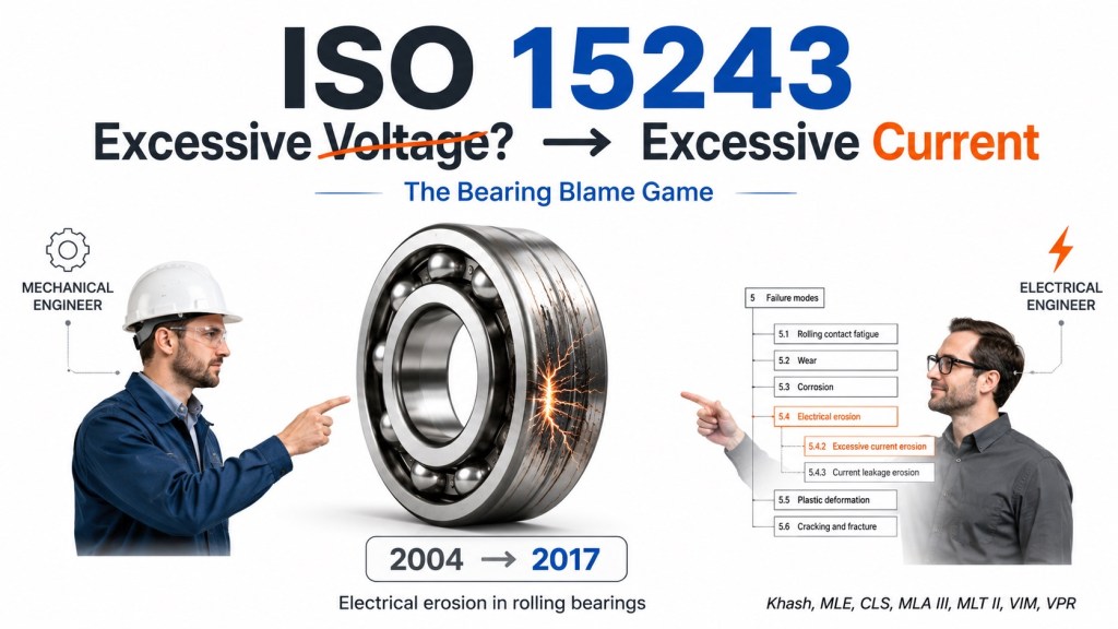
ISO 15243 and the Great Bearing Blame Game
From “Excessive Voltage” to “Excessive Current” — why the wording matters
By Khash
In ISO 15243, the old 2004 version is withdrawn and the 2017 edition is the current published version; ISO states that ISO 15243:2017 classifies rolling bearing damage and failures by failure mode, appearance, characteristics, and possible root causes. (ISO)
The funny but important change you pointed out is this:
Old thinking: “Excessive voltage.”
Current ISO 15243:2017 wording: “Excessive current erosion.”
And mechanically speaking, electrically speaking, and workshop-politically speaking, that change is beautiful.
Because voltage is not what eats the bearing.
Current is what cooks it.
Voltage is the invitation.
Current is the criminal entering the bearing.
The bearing is just the poor security guard standing at the door.
1. Why the wording changed matters
The older wording, “excessive voltage,” made many people focus only on voltage measurement. So the electrical team would come with a meter, check voltage, check insulation, check grounding, smile confidently, and say:
“Electrically everything is fine. Please check lubrication.”
Then the mechanical team would open the bearing and find grey raceways, craters, fluting, black grease, and say:
“Lubrication did not draw these perfect washboard lines. This bearing was electrocuted.”
The newer wording, “excessive current erosion,” is more physically accurate because bearing electrical erosion is damage caused by electric current passing through the rolling contact. SKF defines electrical erosion as macro- or microcraters caused by local melting when damaging electric current passes through bearing rolling contacts.
So the best practical sentence is:
Voltage creates the possibility. Current creates the damage.
Or, more workshop style:
Voltage knocks. Current burns the house.
2. ISO 15243:2017 classification
ISO 15243:2017 classifies bearing failure modes into six main groups and subgroups based mainly on visible distinctive appearance in service, while also admitting the practical truth that it is not always easy to separate root cause from visible symptom.
In the ISO 15243:2017 classification image you shared, electrical erosion is listed as:
| ISO 15243:2017 group | Failure mode |
|---|---|
| 5.4 | Electrical erosion |
| 5.4.2 | Excessive current erosion |
| 5.4.3 | Current leakage erosion |
That is very useful in the field because it separates high-current damage from low-current leakage damage.
3. Excessive current erosion vs current leakage erosion
A. Excessive current erosion — the “arc welding inside the bearing” case
Excessive current erosion is usually more dramatic. It involves higher current, sparking, local overheating, melting, welding, and crater formation. SKF describes excessive current erosion as large craters in raceways and rolling elements, sometimes with discoloured or burnt lubricant from local overheating.
Typical causes include:
- welding current passing through the bearing,
- poor welding return clamp location,
- severe grounding fault,
- electrical fault current through shaft/bearing,
- lightning or large electrical discharge event,
- incorrect maintenance practice,
- current path through gearbox, motor, pump, fan, or roll bearing.
Practical appearance:
- large craters,
- burn marks,
- blackened grease,
- local melted areas,
- pitting larger than normal EDM microcraters,
- rough arc-damaged raceway or roller surface.
Workshop translation:
Somebody used the bearing as an electrical cable, but forgot to ask the bearing.
B. Current leakage erosion — the “silent assassin” case
Current leakage erosion is usually more subtle at first. It is often associated with VFD-driven motors, shaft voltage, common-mode voltage, poor high-frequency grounding, bad bonding, poor cable shielding, and current discharge through the lubricant film.
SKF describes current leakage erosion as shallow craters close to each other; with time, these craters can develop into fluting on raceways.
Typical causes include:
- VFD/PWM drive systems,
- shaft voltage discharge,
- high-frequency circulating current,
- poor motor grounding,
- poor bonding between motor and driven machine,
- long VFD cable,
- poor shield termination,
- insulated motor bearing without shaft grounding,
- metallic coupling transferring shaft voltage to driven equipment,
- poor common-mode current return path.
Practical appearance:
- grey/frosted raceway,
- microcraters under magnification,
- washboard fluting,
- blackened or degraded grease,
- bearing noise,
- vibration increase,
- repeated bearing replacement with same failure.
Workshop translation:
The bearing did not fail. It was slowly EDM-machined while everyone was arguing about grease.
4. Why mechanical and electrical teams fight about this
This is one of the funniest and most expensive reliability arguments in industry.
The mechanical team says:
“The bearing is fluted. It is electrical.”
The electrical team says:
“We checked voltage. It is normal.”
The mechanical team says:
“The raceway looks like a barcode.”
The electrical team says:
“Maybe your grease has Wi-Fi.”
The bearing says nothing, because it has already resigned.
The root of the argument is simple: many electrical bearing currents are high-frequency, intermittent, path-dependent, and not visible with ordinary electrical checks. ABB explains that common-mode current in AC drive systems seeks the path of least impedance, and if the intended protective earth path has high impedance, some current can be diverted through unintended paths. (library.e.abb.com)
That means a normal continuity check may say “ground is fine,” but at high frequency the current may still prefer the shaft, coupling, driven equipment, or bearing.
In electrical reliability, low resistance is not the full story. At high frequency, impedance matters:
[
Z = R + j2\pi fL
]
A long round earth wire may look good with a multimeter but behave poorly at high frequency because inductance becomes significant.
Workshop translation:
The multimeter says yes. The oscilloscope says no. The bearing invoice says congratulations.
5. Why bearings in driven equipment also get blamed on mechanics
This is especially important for pumps, fans, gearboxes, conveyors, rolls, and other driven machines connected to VFD motors.
ABB explains that if a motor shaft is connected through a metallic coupling to grounded driven machinery, part of the inverter common-mode current may flow through the motor bearings, shaft, driven machinery, and back to the inverter; if the driven machine shaft has no direct ground contact, current may flow through gearbox or machine bearings, and those bearings may be damaged before motor bearings. (library.e.abb.com)
That means the failed bearing may not be inside the motor.
It may be in:
- pump bearing housing,
- fan bearing,
- gearbox input shaft bearing,
- conveyor pulley bearing,
- roll bearing,
- compressor bearing,
- driven equipment support bearing.
This is why the mechanical team often receives the failed bearing and the electrical team says:
“But the motor bearing is fine.”
Yes. Because the pump bearing sacrificed itself.
The current found a better route.
6. The practical physics: why current destroys the bearing
A rolling bearing normally runs with a thin lubricant film between roller and raceway. That film is good mechanically but can behave like an electrical insulator.
So voltage builds across the film. When the electrical stress becomes high enough, the film breaks down and a discharge occurs.
The discharge creates:
- local melting,
- microcraters,
- rehardened brittle material,
- annealed softer zones,
- oxidized debris,
- lubricant carbonization,
- surface roughness,
- fluting after repeated rolling.
SKF describes the mechanism of excessive current erosion as electric current passing through the bearing, causing localized heating, melting/welding, and crater formation.
In practical words:
Each spark is tiny. Millions of tiny sparks become a failed bearing.
At first, it looks like frosting.
Then it looks like pitting.
Then it becomes fluting.
Then vibration rises.
Then everyone attends a meeting.
7. Typical visual clues
Excessive current erosion
Look for:
- large craters,
- arc burns,
- melted spots,
- black or burnt grease,
- severe local overheating,
- damage on rolling elements and raceways,
- welding-current history,
- maintenance activity before failure.
Current leakage erosion
Look for:
- grey dull raceway,
- frosted surface,
- microcraters under microscope,
- washboard fluting,
- blackened grease,
- repeated fine lines across the raceway,
- high-frequency bearing noise,
- VFD-driven motor nearby,
- metallic coupling to driven equipment.
SKF notes that fluting is most commonly attributed to damaging electric current passing across the bearing, although washboard-like marks can sometimes be caused by vibration, so confirmation should include magnification and electrical investigation.
That last point matters. Not every line is electrical. But when the pattern, grease, operating history, and VFD system all point the same way, stop blaming grease alone.
8. The famous electrical-team sentence: “But voltage was normal”
This is where the ISO wording helps.
The standard is not saying the bearing was damaged by “excessive voltage erosion.”
It says excessive current erosion.
That matters because a voltage reading alone does not prove the absence of damaging current. NEMA states that shaft voltages can result in destructive currents through motor bearings, producing bearing pitting, shaft scoring, and eventual bearing failure. (NEMA)
So the correct reliability question is not only:
“What voltage did you measure?”
The better questions are:
- Where did the current return?
- Was there shaft voltage discharge?
- Was there common-mode current?
- Was the VFD cable shield terminated correctly?
- Was bonding high-frequency effective?
- Was the motor shaft grounded?
- Were bearings insulated?
- Was the driven equipment bonded?
- Was the coupling metallic or insulated?
- Was welding current allowed through the bearing?
- Was the oscilloscope used, or only a multimeter?
Workshop translation:
A bearing does not care that the electrical report looked clean. It only cares whether current passed through the contact.
9. How the blame game usually happens
Scene 1: The bearing fails
Mechanical opens the bearing.
Findings:
- fluting,
- craters,
- black grease,
- raceway frosting.
Mechanical says:
“Electrical erosion.”
Electrical says:
“Impossible. We have grounding.”
Bearing says:
“Grounding where? At 50 Hz or at VFD switching frequency?”
Scene 2: The lubrication gets blamed
Electrical says:
“Maybe grease problem.”
Mechanical says:
“Grease did not create parallel washboard tracks with EDM microcraters.”
Lubrication team says:
“Please do not drag us into your divorce.”
Scene 3: The motor gets replaced
New bearing installed.
Same VFD.
Same cable.
Same grounding.
Same coupling.
Same shaft voltage.
Same failure.
Now everyone says:
“Bad batch of bearings.”
The bearing manufacturer quietly opens ISO 15243 and points to 5.4.
10. Practical RCA method for electrical bearing damage
Step 1: Preserve the evidence
Do not wash the bearing immediately.
Record:
- grease color,
- grease texture,
- smell,
- raceway appearance,
- roller appearance,
- cage condition,
- fluting direction,
- damaged bearing location,
- motor DE/NDE,
- driven equipment bearing position,
- coupling type,
- VFD information.
Step 2: Inspect under magnification
Electrical erosion can be invisible to the naked eye in early stages. SKF recommends magnification to confirm craters and notes that small craters may be hard to see without magnification.
Look for:
- microcraters,
- molten edges,
- re-solidified material,
- fluting,
- grey frosting,
- black grease,
- current path evidence.
Step 3: Separate electrical erosion from lookalikes
| Damage | Can look similar | How to separate |
|---|---|---|
| Electrical fluting | vibration washboarding | check microcraters and electrical history |
| Current leakage pitting | corrosive pitting | check crater shape and grease condition |
| False brinelling | fluting | false brinelling occurs at roller spacing during standstill |
| Abrasive wear | grey raceway | abrasive wear has cutting/scratching, not EDM craters |
| Smearing | electrical damage | smearing shows sliding/adhesive transfer |
Step 4: Investigate the electrical system
Check:
- VFD type,
- carrier frequency,
- motor cable length,
- cable shield type,
- shield termination,
- 360° bonding,
- motor frame grounding,
- driven machine grounding,
- motor-to-load bonding,
- shaft voltage,
- shaft grounding ring condition,
- insulated bearing arrangement,
- coupling conductivity,
- welding history,
- nearby electrical faults.
Step 5: Measure correctly
Use:
- oscilloscope,
- shaft voltage probe,
- high-frequency current clamp where applicable,
- electrical discharge detector,
- bearing inspection microscopy,
- vibration analysis,
- grease analysis.
A multimeter alone is not enough for VFD-related bearing currents.
Workshop translation:
Using only a multimeter for VFD bearing current is like using a bathroom scale to measure vibration. Nice tool, wrong problem.
11. Corrective actions that actually stop the problem
A. Stop welding current through bearings
This is the easiest one.
Rules:
- attach welding return clamp close to welding point,
- never allow current path through bearings,
- isolate shaft when necessary,
- lock out rotating equipment correctly,
- inspect bearings after suspect welding activity.
If the bearing has welding-current damage, the corrective action is not grease. It is welding discipline.
B. Install proper shaft grounding
A shaft grounding ring or brush gives shaft current a controlled path that bypasses bearing contacts.
Good practice:
- install at correct location,
- keep contact surface clean,
- avoid paint, rust, oil film, and contamination,
- bond to frame with short low-impedance path,
- inspect periodically,
- verify shaft voltage after installation.
C. Use insulated bearings correctly
Options include:
- insulated outer ring,
- insulated inner ring,
- hybrid bearing with ceramic rolling elements,
- insulated housing sleeve,
- insulated bearing arrangement per OEM design.
SKF lists insulated bearings, hybrid bearings, and insulating sleeves as possible alternatives when grounding corrections do not solve electrical erosion.
Important warning:
Insulating one bearing can move the current to another bearing if the current path is not understood.
That is how motor bearing protection becomes pump bearing destruction.
D. Improve high-frequency bonding
For VFD systems, grounding must be good at high frequency.
Use:
- short, wide bonding straps,
- clean metal contact,
- motor-to-base bonding,
- driven equipment-to-base bonding,
- motor-to-driven equipment bonding,
- proper shield termination,
- no paint under bonding points.
ABB explains that common-mode current seeks the path of least impedance, and unintended current paths can appear when intended grounding paths have too much impedance. (library.e.abb.com)
E. Correct VFD cabling
Use:
- proper VFD-rated cable,
- symmetrical grounding conductor arrangement,
- continuous shield or armour,
- 360° shield termination,
- short PE connections,
- correct grounding at drive and motor,
- avoid shield pigtails,
- minimize cable length where possible.
Poor VFD cabling is one of the main reasons electrical teams and mechanical teams keep meeting beside failed bearings.
F. Use common-mode filters where needed
Correct filter selection may include:
- common-mode choke,
- dV/dt filter,
- sine-wave filter,
- output reactor depending on the problem.
Not every filter solves every bearing-current mechanism. The solution must match the failure mode.
G. Protect driven equipment
For driven equipment bearings:
- check metallic coupling current path,
- consider insulated coupling,
- bond motor and driven machine frames,
- install shaft grounding on motor side,
- inspect driven bearing for fluting,
- consider insulation/hybrid bearing only after path analysis.
ABB specifically warns that driven machine bearings can be damaged before motor bearings if current flows through the driven machine path. (library.e.abb.com)
Workshop translation:
If you insulate the motor and forget the driven machine, congratulations: you have promoted the pump bearing to electrical fuse.
12. Practical mechanical/electrical agreement form
To avoid the usual “not our problem” tournament, both teams should sign off on the RCA.
Mechanical team confirms:
- bearing damage morphology,
- fluting/crater evidence,
- grease condition,
- bearing position,
- load condition,
- lubrication condition,
- mechanical fit/alignment,
- whether non-electrical causes are possible.
Electrical team confirms:
- VFD present or not,
- shaft voltage measured,
- grounding/bonding checked,
- cable shielding checked,
- carrier frequency reviewed,
- shaft grounding condition,
- insulated bearing arrangement,
- welding current path history,
- driven equipment grounding path.
Reliability team confirms:
- failure mode according to ISO 15243,
- primary and secondary causes,
- corrective action owner,
- verification method,
- post-repair monitoring.
This prevents the classic answer:
“Mechanical changed the bearing, electrical checked the panel, and the failure returned exactly on schedule.”
13. Best failure-report wording
You can write:
The bearing damage is consistent with ISO 15243 electrical erosion. The observed features should be classified under ISO 15243:2017 failure mode 5.4, with further distinction between 5.4.2 excessive current erosion and 5.4.3 current leakage erosion based on crater size, surface morphology, lubricant condition, and electrical operating history. The change from earlier “excessive voltage” terminology to “excessive current erosion” is technically significant because voltage alone does not damage the bearing unless a damaging current passes through the rolling contact. Root cause investigation must therefore include shaft voltage, current path, grounding, bonding, VFD cabling, insulation strategy, coupling conductivity, driven equipment grounding, and welding-current history.
14. The one-line lesson
Do not ask only, “Was there voltage?”
Ask:
“Where did the current go?”
Because the bearing does not fail from electrical vocabulary.
It fails when current uses the rolling contact as a shortcut.
15. Final practical takeaway
The ISO wording change is small, but the reliability lesson is big.
Voltage is the suspect.
Current is the weapon.
The bearing is the victim.
The microscope is the witness.
The oscilloscope is the detective.
Mechanical and electrical teams are both in the courtroom.
And the verdict is usually:
Stop blaming the bearing. Find the current path.
Khash
MLE, CLS, MLA III, MLT II, VIM, VPR
 Rolling Bearing Reliability