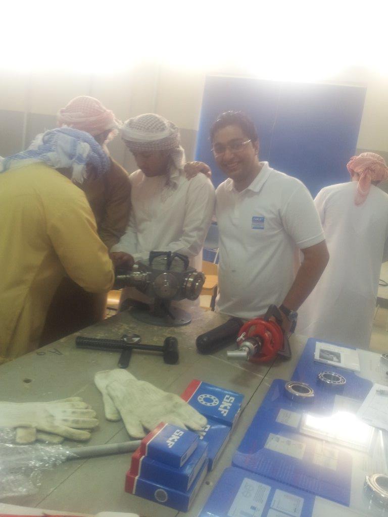
I used to take these mounting and dismounting demonstration units , with their bearings and SKF tools always in my car when I would deliver an onsite training for the practical part
From Force to Control: Khash’s Hands-On Experience with the SKF TMDS 6 and TMDS 9
How two bearing demonstration systems transformed mounting and dismounting from written procedures into practical lessons in precision, safety and equipment reliability
The photograph from Khash’s SKF training session captures the character of genuine technical learning. Around the workbench are bearing components, specialist tools, protective gloves, hydraulic equipment and familiar blue SKF cases. Participants are gathered close to the demonstration unit, not merely watching a presentation but examining the components and following the mounting process step by step.
For Khash, this hands-on environment provided something that diagrams and catalogues alone could not: a direct understanding of how a bearing responds to heat, hydraulic pressure, axial movement, mechanical force and changes in internal clearance.
Bearing installation can appear straightforward until the technician encounters an interference fit, a tapered bore, an adapter sleeve or a housing that offers very little access for a puller. The SKF TMDS 6 and TMDS 9 demonstration systems bring these conditions into a controlled training environment. SKF’s instructions emphasize that bearing reliability depends on selecting the correct mounting method, using suitable tools and maintaining clean working conditions. These principles became the foundation of Khash’s experience with both systems.
Learning that bearing mounting is a controlled process
One of Khash’s most important lessons was that bearing work should not be approached as an exercise in applying the greatest possible force. It is a controlled engineering process.
Every installation requires several decisions:
- Which bearing ring has the interference fit?
- Is the bearing bore cylindrical or tapered?
- Is the bearing being installed directly on a shaft, in a housing, on an adapter sleeve or with a withdrawal sleeve?
- Should the fit be achieved mechanically, thermally or hydraulically?
- How will the mounting result be measured?
- How will the bearing later be removed without damaging the shaft, housing or bearing?
The TMDS equipment allowed Khash to work through these questions physically. Instead of memorizing isolated procedures, he could see the relationship between the bearing design, the seating arrangement and the selected tool.
SKF TMDS 6: establishing the fundamentals
The TMDS 6 is built around six shaft arrangements on a turning demonstration table. Its exercises include spherical roller bearings on tapered shaft seats, ball bearings on cylindrical seats, bearings mounted with adapter and withdrawal sleeves, a cylindrical roller bearing and a self-aligning ball bearing installed in a housing. It also enables a direct comparison between conventional mechanical removal and the SKF Oil Injection Method.
This range made the TMDS 6 an effective foundation platform for Khash. Each shaft introduced a different maintenance problem, but the exercises remained structured enough for him to concentrate on the underlying principles.
Mechanical mounting and correct force transmission
The smaller ball-bearing exercise demonstrated the use of the SKF TMFT 36 fitting tool. Khash learned that the impact ring and sleeve must be selected to direct the mounting force through the ring being fitted.
This was a deceptively important exercise. The fitting tool did not simply make the work easier; it established a repeatable method. The bearing could be kept square to its seating, and the mounting force could be applied in a controlled direction rather than through an improvised drift or an unsuitable striking surface.
The lesson was that even a relatively small bearing deserves a defined installation procedure. A bearing should not be judged only by its dimensions or purchase price. Its performance still depends on the quality of the fit, the cleanliness of the seating and the way the mounting force is transmitted.
Understanding the SKF Drive-up Method
The most technically significant TMDS 6 exercise for Khash involved mounting a spherical roller bearing with a tapered bore. As the bearing is driven farther onto the taper, the inner ring expands and the bearing’s internal radial clearance decreases. The final position therefore cannot be established safely by appearance or by subjective “feel.”
The SKF Drive-up Method converts this operation into a measurable sequence. A hydraulic nut first moves the bearing to a defined starting position at a calculated hydraulic pressure. The bearing is then driven through a specified axial distance, monitored with a dial indicator.
For the TMDS 6 exercise using the 22320 EK/C3 bearing on the designated tapered shaft, SKF specifies a starting pressure of 4.1 MPa and an axial drive-up distance of 0.60 mm. On the adapter-sleeve exercise, the manual gives different values because two mating surfaces slide during mounting. These figures are specific to the demonstrator configuration rather than universal field settings, but they clearly illustrate why the installation conditions must be defined before pressure is applied.
For Khash, this was where bearing mounting became a metrology exercise rather than a mechanical approximation. Pressure established the starting reference; axial displacement established the final fit. The process could be recorded, checked and repeated by another technician.
Comparing drive-up with radial-clearance reduction
The TMDS 6 also supports the traditional radial-clearance-reduction method. Before installation, the technician measures the bearing’s internal radial clearance with a feeler gauge. As the bearing is driven onto the tapered seating, further measurements show how much clearance has been removed.
Working with both methods helped Khash understand that they are two ways of controlling the same physical result: the expansion of the inner ring and the resulting change in bearing clearance. The traditional method demands careful feeler-gauge technique, while the Drive-up Method uses pressure and axial displacement to produce a more standardized procedure.
The comparison reinforced a broader maintenance principle: measurements should govern the work. A technician should be able to explain not only that the bearing has been tightened, but how the final fit was determined.
Experiencing the effect of oil injection
Another memorable TMDS 6 exercise compared two ball bearings mounted on cylindrical shaft seats. One bearing was removed conventionally with a puller, while the other used high-pressure oil introduced between the bearing bore and its seating.
The oil forms a pressurized film that reduces the resistance created by the interference fit. The puller still controls the axial movement, but substantially less mechanical effort is required. SKF describes the Oil Injection Method as a means of reducing effort and avoiding unnecessary damage to the mating components.
For Khash, the difference was easier to appreciate physically than theoretically. The conventional arrangement demonstrated the force that may be required to break a dry interference fit. The oil-assisted arrangement showed how the same job could be completed more smoothly when the contact pressure was hydraulically relieved.
This experience also highlighted the importance of preparation. The technician must identify the correct hydraulic connection, inspect the hose and fittings, secure the puller, close the pump-release valve and continue supplying oil while the bearing is withdrawn.
Respecting stored energy and safe restraint
Hydraulic dismounting introduced an equally important safety lesson. When a bearing is released from a tapered seating, it may move suddenly and with considerable force. SKF therefore requires a hydraulic nut or locking nut to remain on the shaft, with a controlled gap, so that it acts as a stop and prevents uncontrolled ejection.
Khash’s experience with the demonstrator made this warning tangible. The restraint is not a minor procedural detail added to a manual; it is part of the mechanical system. Pressure should be applied only after the technician has considered where every component could move when the fit releases.
Using heat as an engineering tool
Both TMDS systems demonstrated induction heating for bearings with cylindrical bores. The objective is to expand the bearing inner ring sufficiently for it to slide onto the shaft without excessive mechanical force.
The SKF procedures used in the exercises call for heating the bearing approximately 80 to 90 °C above the shaft temperature while keeping the bearing below 125 °C. They also specify the use of clean gloves or a clean, lint-free cloth when handling the heated component.
For Khash, induction heating illustrated the importance of timing and preparation. Before the bearing reaches the target temperature, the seating must already be clean, lightly lubricated where specified and ready for installation. The technician must know the correct orientation and the required final shoulder position.
Once removed from the heater, the bearing must be moved promptly and kept square to the shaft. Hesitation allows the inner ring to cool and contract before reaching its final position. Misalignment can cause it to grip partway along the seating.
The exercise therefore combined thermal knowledge with organization. Successful hot mounting begins before the heater is switched on.
SKF TMDS 9: broadening the maintenance challenge
Where the TMDS 6 established the core methods, the TMDS 9 expanded the range of bearing arrangements and tool-access problems. Its nine shaft exercises cover ball bearings mounted on shafts and in housings, angular-contact ball bearings, spherical roller bearings with cylindrical and tapered bores, adapter- and withdrawal-sleeve arrangements, a self-aligning ball bearing in a housing, two differently sized deep-groove ball bearings and a separable cylindrical roller bearing.
Khash found that the TMDS 9 demanded more than familiarity with individual tools. It required planning the complete job:
- determining the bearing orientation;
- identifying the interference-fit ring;
- considering whether the puller could reach behind the bearing;
- deciding whether an internal extractor was required;
- preparing for the sequence in which several components had to be mounted;
- and understanding how spacers, nuts, washers and sleeves contributed to the final arrangement.
Working with angular-contact bearings
One of the distinctive TMDS 9 exercises involved a pair of 7308 BECBP angular-contact ball bearings. The two bearings are heated and mounted in an O, or back-to-back, arrangement without misalignment, with their inner rings positioned against the appropriate abutment.
This exercise showed Khash that bearing orientation can be just as important as fit. An angular-contact bearing is designed to carry load in a particular axial direction. When two are installed as a pair, their arrangement affects the support characteristics of the shaft system.
The job therefore required visual confirmation before installation. Once heated bearings begin to cool on an interference-fit shaft, there is little time to reconsider their orientation.
Selecting the removal method from available access
The TMDS 9 shaft-and-housing exercises demonstrated that bearing removal is often governed by access rather than bearing size alone.
For one 6208 bearing configuration, a conventional puller can engage the bearing. In another configuration, access behind the bearing is restricted, requiring an internal puller inserted through the bearing bore and expanded behind it. A slide hammer is then used to extract the bearing.
For Khash, this was a practical lesson in maintenance planning. A puller should not be selected simply because its nominal capacity exceeds the expected withdrawal force. The technician must also establish where its arms or collets will react, whether there is sufficient clearance and whether the load will remain centered.
This exercise was particularly relevant to field maintenance, where bearings are frequently surrounded by housings, shoulders, seals or adjacent components that limit access.
Comparing dry and oil-assisted removal again
The eighth TMDS 9 shaft carries two different ball bearings and demonstrates the considerable difference between conventional puller removal and removal assisted by pressurized oil. The larger 6214 bearing is removed while oil is introduced between the bearing and shaft seating, whereas the 6212 exercise uses conventional puller force after the components have cooled.
Repeating this comparison on a second platform strengthened Khash’s understanding of hydraulic assistance. Oil injection was no longer simply an impressive demonstration. It became a method whose value could be predicted from the size of the interference fit, the shaft design and the availability of oil ducts and grooves.
Handling a separable cylindrical roller bearing
The TMDS 9 also includes an NU 2212 ECP cylindrical roller bearing. Its separable design permits the cage and roller assembly to be removed independently, leaving the interference-fitted inner ring on the shaft.
The inner ring can be mounted by induction heating. For dismounting, the exercise uses a heated aluminium ring placed around the bearing inner ring, transferring heat rapidly so that the ring expands and can be withdrawn.
This arrangement gave Khash a clearer appreciation of bearing construction. A cylindrical roller bearing is not always handled as one complete unit. Understanding which components separate, which ring carries the interference fit and how heat can be applied locally is essential to choosing an efficient removal method.
How the two systems complemented each other
Khash’s experience suggested that the TMDS 6 and TMDS 9 should not be viewed as competing versions of the same trainer.
The TMDS 6 provided depth in several fundamental procedures. Its larger spherical roller-bearing exercises placed strong emphasis on the SKF Drive-up Method, radial-clearance measurement, hydraulic nuts, adapter and withdrawal sleeves, oil injection and controlled thermal mounting.
The TMDS 9 provided greater breadth. It added angular-contact bearing orientation, alternative housing-removal techniques, internal extraction, a wider selection of pullers and several shaft arrangements that required the technician to consider component sequence and tool access.
In practical terms, the TMDS 6 taught Khash how the principal mounting methods work. The TMDS 9 challenged him to decide where and why each method should be used.
Skills carried into industrial maintenance
The most valuable outcome of the training was not familiarity with a particular model of demonstration unit. It was the development of a repeatable maintenance mindset.
Khash learned to begin by identifying the bearing and seating arrangement rather than immediately selecting a tool. He learned to clean and inspect the mating surfaces, determine which ring required the interference fit, calculate or confirm the mounting condition and prepare all tools before applying heat or hydraulic pressure.
He also developed greater respect for measurement. A dial indicator, pressure gauge, thermometer and feeler gauge were not secondary accessories. Each provided evidence that the work had reached the required condition.
The training also strengthened his approach to dismounting. Before applying force, he learned to identify the reaction point, provide safe restraint, confirm the puller’s alignment and consider whether hydraulic oil could reduce the required effort. This approach protects not only the bearing but also the shaft, sleeve, housing and surrounding equipment.
A lasting change in maintenance philosophy
Khash’s experience with the SKF TMDS 6 and TMDS 9 ultimately changed the way bearing work could be understood.
A bearing is a precision machine component, and its installation should be treated as a precision operation. Heat, pressure and mechanical force are useful only when they are controlled. Cleanliness is part of the technical procedure. Safety restraints are part of the mechanical design. Measurements are what turn an individual technician’s actions into a repeatable maintenance standard.
The workshop photograph therefore represents more than a training demonstration. It captures the point at which written procedures became physical knowledge: the feel of a bearing moving under hydraulic pressure, the urgency of positioning a heated inner ring, the resistance of a dry interference fit and the discipline required to perform each operation safely.
For Khash, the TMDS 6 supplied the foundations. The TMDS 9 expanded those foundations into a broader problem-solving capability. Together, they reinforced a principle applicable throughout rotating-equipment maintenance: bearing reliability begins long before the machine starts turning.
 Rolling Bearing Reliability