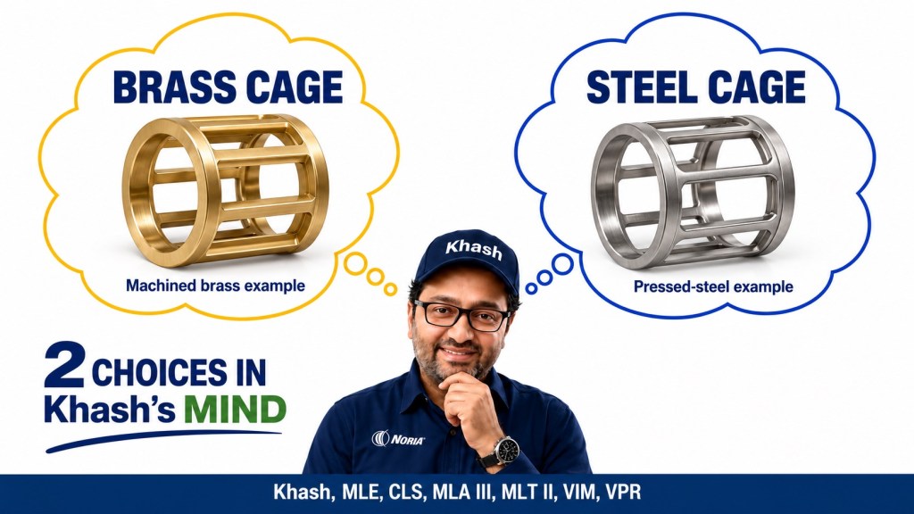
Brass Cage or Steel Cage in Critical Rolling Bearing Applications
A practical technical article by Khash
Khash, MLE, CLS, MLA III, MLT II, VIM, VPR
The better cage is the complete design that controls rolling-element motion, receives adequate lubrication, and survives the actual duty. Cage metal alone cannot establish which bearing will perform better.
Machined brass deserves serious consideration in severe-duty centrifugal-pump angular contact bearings and demanding motor applications. Engineered steel cages are equally legitimate candidates in motors, fans, gearboxes and rolling mills. Each decision needs a particular bearing execution and an operating envelope.
The distinction starts with construction. A lightweight pressed-steel cage, a surface-hardened steel cage, a substantial machined-steel cage and a steel pin cage are different engineering solutions. Likewise, pressed brass, a riveted machined-brass assembly and a one-piece machined-brass cage should not be treated as one product.
The manufacturer examples below are documented products and published cases. Calculations identified as illustrative use stated assumptions; they are not measurements from a customer’s machine.
1. First identify what is actually being compared
| Cage construction | What it means | What must be evaluated |
|---|---|---|
| Pressed or stamped steel | Sheet material is formed into a relatively thin cage; construction may include rivets or separate halves. | Pocket shape, joints, stiffness, mass and lubricant access. |
| Surface-treated pressed steel | A stamped cage receives a treatment intended to improve its working surfaces. | The exact treatment and the complete design’s fatigue and wear capability. |
| Machined brass | Brass stock or a casting is machined into the cage; one-piece and assembled designs exist. | Alloy, pocket geometry, guidance, joints, lubrication and dynamic qualification. |
| Machined steel | A substantial cage is machined from steel. | Structural strength, guidance, surface condition and sliding-contact lubrication. |
| Steel pin or stud construction | Retaining members locate rollers through or at their ends. | Roller construction, pin or stud details, lubrication and mill duty. |
These distinctions are reflected in manufacturer guidance: Schaeffler separately classifies pressed cages and solid brass/steel cages, while SKF distinguishes low-carbon sheet-steel cages from machined structural-steel cages. A cage described as steel is therefore not necessarily made from the same hardened steel as the bearing rings. schaeffler.com
The familiar comparison of a thick machined-brass cage with a thin stamped-steel cage changes several things simultaneously: material, section thickness, pocket contact, stiffness, mass and sometimes guidance. A successful substitution cannot automatically be credited to brass alone.
Conversely, replacing a robust machined-steel cage with brass is not automatically an upgrade. In a mill bearing, the original steel construction may be essential to its particular roller arrangement.
A useful purchasing description identifies the alloy or material family, manufacturing method, guidance and complete bearing suffix. “Heavy-duty brass” is too incomplete to approve a critical substitution.
Brass and bronze should also remain distinct in specifications. Use the manufacturer’s material designation rather than identifying a cage by its yellow colour.
What the material properties actually tell us
Brass is a copper–zinc alloy family; steel is an iron-based alloy family. Their physical properties differ, but a material-property table is not a finished-cage performance ranking.
For scale, the following published values compare C36000 brass as an illustrative alloy with general structural-steel data. C36000 is not being specified here as the alloy in every bearing cage.
| Property | C36000 brass reference | Structural-steel reference | Practical implication |
|---|---|---|---|
| Density | About 8.5 g/cm³ | About 7.85 g/cm³ | At equal volume, this brass is heavier. A stamped cage’s low mass mainly reflects its small material volume. |
| Elastic modulus | About 97 GPa | About 210 GPa | The steel material is stiffer, but finished-part stiffness also depends strongly on section geometry. |
| Linear thermal expansion | About 20.5 × 10⁻⁶/°C, averaged over 20–300°C | About 12 × 10⁻⁶/°C up to 100°C | Differential expansion belongs in pocket and guidance-clearance design. |
The brass values come from the Copper Development Association; the steel values come from SSAB. The quoted temperature intervals differ, so the expansion figures show a material tendency rather than an exact operating-clearance calculation. C36000 Alloy
Stiffness, yield strength, fatigue resistance, impact toughness and sliding-wear resistance are separate properties. A thicker brass section can have substantial structural capacity even though its material modulus is lower. A surface-treated steel pocket can behave differently from untreated steel. For selection, ask for the finished design’s qualification; a raw alloy’s tensile strength cannot predict cage life by itself.
2. Understand the cage’s job and its guidance
The cage keeps rolling elements separated and appropriately spaced, guides them through unloaded regions and, in many separable designs, retains them during handling. Its condition influences the stability of rolling-element motion. NSK Global
The main external load travels through the rings and rolling elements. The cage experiences the forces needed to guide and coordinate those elements, together with inertia and frictional forces. It is not a second radial load-carrying structure that simply adds capacity when made thicker.
Consider a roller moving through a bearing. Its traction conditions change as it enters and leaves the loaded region. If its motion departs substantially from the required rolling motion, contacts with the pocket can become more demanding. The engineering objective is to control this behaviour while keeping friction and contact stress acceptable.
Three different guidance arrangements
- Rolling-element guidance: the cage is centred by the balls or rollers.
- Inner-ring guidance: a cylindrical surface on the inner ring guides the cage.
- Outer-ring guidance: a cylindrical surface on the outer ring guides the cage.
Schaeffler explicitly treats guidance as a separate cage characteristic. Its guidance suffixes belong to its own designation system; they should not be transferred automatically to another brand. schaeffler.com
A ring-guided cage introduces an additional sliding interface that requires lubricant. A rolling-element-guided design has its own pocket-contact requirements. Neither guidance method wins every application.
SKF’s large-motor guidance favours certain roller-guided cages for grease lubrication, while purpose-designed ring-guided cages remain valid in other duties. The practical question is whether the actual lubricant reaches the actual guiding surfaces throughout operation. 2012-09-30
Think of guidance and material as two separate selections. A well-supported steel cage may be more stable than an inadequately supported brass cage; a carefully profiled brass pocket may perform better than an older brass pocket.
3. Loads, fatigue life, shock and the minimum-load problem
Heavy bearing load does not mean the cage carries that load
The basic fatigue-life relationship is:
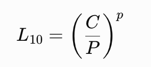
Here \(L_{10}\) is in millions of revolutions, \(C\) is basic dynamic load rating, \(P\) is equivalent dynamic load, and \(p=3\) for ball bearings or \(10/3\) for roller bearings. This concerns rolling-contact fatigue at a statistical reliability of 90%. NSK Global
There is no separate “brass bonus” in this equation. If two executions have identical \(C\), \(P\) and speed, their basic calculated fatigue lives are identical. Their actual service lives can still differ because of cage durability, lubrication, wear or other damage.
Illustrative calculation: suppose a redesigned roller bearing has 10% more dynamic capacity, with the same applied load.
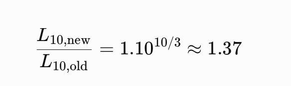
Its calculated basic fatigue life rises about 37%. That benefit comes from the increased rating. To credit the cage, establish how its design enabled the rating increase, for example by accommodating additional rollers.
Do not interpret this calculation as a prediction of cage-fatigue life or a guarantee of 37% longer service in contaminated oil.
High load and violent dynamics require different checks
A steady radial load, a short impact, rapid acceleration and a reversing load are different inputs. Two machines with the same maximum radial force can impose very different cage duties.
NSK identifies shock, vibration, excessive speed, acceleration/deceleration, poor lubrication and misaligned mounting among causes of cage damage. These conditions can damage machined-brass cages as well as pressed-steel cages. NSK Americas
For a critical selection I would request the load spectrum, start/stop profile and known shock events. A manufacturer’s validated stronger cage is valuable when it addresses those conditions. Merely increasing cage thickness could also increase inertia and alter lubricant flow.
Too little load can be damaging
A rolling bearing needs sufficient load for satisfactory rolling under its particular operating conditions. High speed and lubricant resistance can make a lightly loaded bearing especially difficult. A very large fatigue-life number does not establish that an oversized bearing will operate reliably.
SKF’s cylindrical-roller-bearing development tests specifically investigated roller slip at very low load. Its engineered, inner-ring-guided steel JB design reduced slip relative to the tested brass execution. That result demonstrates the importance of geometry and guidance; it does not permit arbitrary steel-for-brass substitutions. Evolution
This produces two separate selection questions:
- Can the bearing survive the maximum and accumulated loads?
- Does it have enough load during its least-loaded operating periods?
A stronger cage may tolerate more abuse while the underlying rolling problem remains.
4. Speed, acceleration, friction and heat
Shaft rpm is only a starting point
Use the mean-diameter speed factor as an initial comparison:
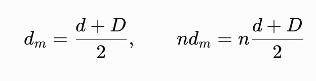
Here \(d\) and \(D\) are bearing bore and outside diameter in millimetres, and \(n\) is shaft speed in revolutions per minute. This conventional index is not the exact rolling-element pitch diameter or a universal permissible-speed criterion.

Keep thermal and mechanical ratings separate
Reference or thermal speed concerns heat generation and heat removal under defined conditions. Limiting or mechanical speed concerns additional constraints such as component behaviour and cage stability. The permissible speed in the machine requires assessment of both. SKF explains this distinction and the need to consider lubrication, cooling and mounting conditions. cdn.skfmediahub.skf.com
A higher mechanical limit does not create the cooling needed to reach it. An oil-circulation limit cannot be used as a grease-lubrication limit.
The cage itself also rotates at a speed governed by bearing kinematics; its speed is not generally equal to shaft speed. Manufacturer ratings account for geometry and operating assumptions that a simple “steel is lighter” argument leaves out.
Lower mass helps inertia, but does not decide the winner
For a simple rotating-body approximation:
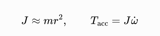
At the same effective radius and angular acceleration, twice the rotating mass requires twice the acceleration torque. This is a teaching approximation, not a cage stress calculation; actual cages have distributed mass and complex contacts.
A lighter cage can therefore be attractive for rapid transients. Nevertheless, the stronger geometry and guidance of a heavier cage may provide a higher validated speed capability. The product tables in Sections 7 and 8 demonstrate why both effects must be considered.
Heat generation can outweigh a material’s thermal conductivity
Bearing friction produces heat according to:
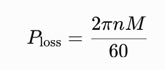
where \(M\) is total friction torque in N·m.
Illustrative calculation: at 3,000 rpm, 0.20 N·m produces about 63 W; 0.50 N·m produces about 157 W. The difference is approximately 94 W.
Those are assumed torque values. They show why an apparently small friction change can matter. Predicting the resulting temperature requires the actual housing, shaft, airflow and oil cooling.
Do not select brass on thermal conductivity alone. A cage that generates less heat or permits better lubricant circulation can outperform a more conductive material.
There is a current manufacturer example: Schaeffler’s 2026 G-series announcement describes replacing machined brass with a steel cage in deep-groove ball bearings for generators to reduce friction and improve relubrication and internal grease capacity. The claim applies to that engineered bearing series. Schaeffler Group
5. Lubrication often decides whether either cage succeeds
A bearing needs lubricant at the rolling contacts and at sliding contacts involving cage pockets, guiding surfaces and, where applicable, roller ends and flanges. Adequate lubricant in the housing does not by itself prove adequate delivery to each contact.
Grease grade is not oil viscosity
Grease contains base oil, thickener and additives. Its consistency and its base-oil viscosity are different properties. NSK also points out that grease quantity depends on speed, available space, housing and the particular grease. NSK Global
Therefore, “both bearings use NLGI 2 grease” is insufficient for a cage comparison. Establish the base-oil viscosity at operating temperature, oil release, replenishment, grease quantity and compatibility with the existing lubricant.
One useful screening parameter is kappa :
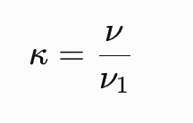
where \(\nu\) is operating viscosity and \(\nu_1\) is the reference viscosity required for the bearing’s size and speed. SKF’s fan guidance uses this relationship when discussing lubricant-film adequacy. It is a rolling-contact lubrication indicator, not a direct calculation of film thickness at every cage contact. Evolution
Illustrative example: if operating viscosity is 12 mm²/s and the required reference is 20 mm²/s, \(\kappa=0.6\). If another qualified lubricant provides 30 mm²/s under the same assumed conditions, \(\kappa=1.5\).
Changing cage metal does not change the first oil into the second. Conversely, choosing ever-higher viscosity can increase friction and make low-load, high-speed operation more difficult. The task is to supply appropriate viscosity and sufficient lubricant, not simply the thickest available grease.
Grease and circulating oil create different operating opportunities
Circulating oil can remove heat and support filtration; grease usually permits a simpler system. Those differences help explain why one bearing can have distinct grease, oil-bath and controlled-circulation speed ratings. NSK Global
For grease-lubricated machinery, review how fresh grease reaches the bearing and where displaced grease exits. For oil systems, review delivery to each bearing, drain capacity, oil level, aeration, temperature and cleanliness.
A change of cage geometry can change free space and flow paths. Reusing the old lubrication procedure without checking the replacement design can obscure a valid bearing improvement.
Brass is not a substitute for a lubricant film
Some brass constructions have useful behaviour against steel under marginal lubrication. Timken discusses this advantage for specific brass spherical-roller cages. The same publication also describes steel-cage features intended to improve lubricant flow and reduce heat. timken.com
Neither statement establishes that a standard metallic cage can run indefinitely without lubrication. A cage may remain intact while the raceways already suffer damage.
In dirty mill, cement or mining service, improve exclusion and removal of contaminants. SKF’s wear research describes how poor lubrication and contamination can modify raceway profiles and lead to damaging local stress concentrations. A more robust cage does not remove those particles. Evolution
6. Temperature and chemical compatibility
Cage-temperature figures are not complete-bearing ratings
SKF’s general material guidance gives steel cages up to 300°C and brass cages up to 250°C. These figures describe cage-material capability within the manufacturer’s guidance. cdn.skfmediahub.skf.com
The machine’s permissible bearing temperature may be much lower because of lubricant life, seal material, ring dimensional stability, operating clearance or the approved equipment specification.
For an illustrative 120°C bearing duty, both quoted metal limits lie above the operating temperature. That comparison alone offers no reason to prefer either cage. The relevant questions concern lubrication, ring treatment, clearance and the complete bearing’s qualification at 120°C.
A pump’s process-liquid temperature is also not automatically the temperature of its bearing oil or rings. Establish the actual thermal path and measured bearing conditions.
EP additives require a formulation-specific decision
SKF’s 2013 motor handbook warns about sulphur-containing EP additives acting aggressively on brass above 100°C. That is a reason to investigate the lubricant/cage combination. cdn.skfmediahub.skf.com
It does not justify declaring every EP lubricant incompatible with brass. ExxonMobil describes a sulphur/phosphorus EP formulation in its Spartan EP range while also specifying protection of copper-containing alloys. Klüber likewise identifies selected synthetic gear oils as compatible with brass, bronze and copper. mobil.com
For a critical bearing, ask the lubricant supplier and bearing manufacturer about the actual finished product, cage alloy, temperature and expected contamination. A copper-corrosion test is useful evidence, but it is not a complete bearing-life validation.
Ammonia exposes the weakness of broad material rules
SKF distinguishes pressed-brass cages susceptible to stress-related cracking in ammonia service from qualified machined-brass constructions. The manufacturing condition and residual stresses matter. Evolution
The practical choice is the compressor manufacturer’s qualified bearing execution. Neither blanket approval nor blanket rejection of every brass cage is justified.
Finally, make the exposure assessment realistic. A bearing isolated from the process by an effective arrangement has a different chemical duty from one lubricated by, or repeatedly contaminated with, the process fluid.
7. NU cylindrical roller bearings in electric motors
An NU bearing is a useful place to challenge the statement that brass automatically makes a motor more reliable. My first questions are: How much radial load reaches this bearing? What happens during acceleration? How is it lubricated? Can the shaft expand freely?
In an NU bearing, the outer ring has two integral flanges and the inner ring has none. Relative axial displacement occurs within the bearing, making it suitable for the nonlocating position. A typical belt-driven motor can use an NU bearing to support substantial radial load at the drive end while another bearing locates the rotor axially. Changing the cage material does not change this function. 2012-09-30
A real comparison: NSK NU213EW and NU213EM
The current NSK specifications provide a useful comparison within one manufacturer and bearing size:
| Published property | NU213EW | NU213EM |
|---|---|---|
| Cage | Pressed steel | Machined brass |
| Bore × outside diameter × width | 65 × 120 × 23 mm | 65 × 120 × 23 mm |
| Basic dynamic load rating, Cr | 132 kN | 132 kN |
| Basic static load rating, C0r | 119 kN | 119 kN |
| Listed grease speed | 4,800 r/min | 4,800 r/min |
| Listed oil-bath speed | 5,600 r/min | 5,600 r/min |
| Mechanical speed with properly designed and controlled forced-circulation oil | 8,500 r/min | 9,500 r/min |
These are manufacturer ratings for the stated lubrication conditions. They are not interchangeable speed limits for any installed motor. The basic load ratings also do not represent an allowable continuous operating load. NSK
The conclusion is specific: these two executions have equal published load ratings and equal listed grease and oil-bath speeds. The brass execution has a higher mechanical speed rating with controlled forced-circulation oil. That difference does not establish longer life in a grease-lubricated motor.
Practical case: a motor running at 2,950 r/min
Consider an illustrative horizontal motor using grease lubrication, operating steadily at 2,950 r/min. Assume its bearing load, fits, operating clearance, grease specification and relubrication procedure satisfy the motor and bearing manufacturers’ requirements.
Both NSK options are below their listed grease speed. For this duty, the catalog provides no grease-speed or load-rating advantage for EM. If the approved steel-cage execution already satisfies the mechanical duty, a criticality label alone does not justify changing it.
Brass becomes a stronger candidate when there is a specific requirement that its execution addresses: severe dynamic cage loading, a validated noise requirement, or a different lubrication and speed regime. Establish that requirement before claiming an improvement.
Being below a catalog speed is only one check. A bearing can overheat below that speed because the actual grease, fill, heat rejection or operating clearance differs from the conditions assumed in selection. Neither cage should be approved by comparing two rpm numbers alone.
The underloaded motor: a stronger cage can miss the problem
Now consider a separate hypothetical motor. Assume the supplier determines that its particular bearing and duty require at least 2.0 kN radial load, but the actual bearing load during a sustained operating condition is 0.7 kN. These are assumed teaching values, not minimum-load ratings for NU213EW or NU213EM.
The bearing receives only 35% of the specified minimum. A brass replacement does not demonstrate that the minimum-load requirement has been met.
SKF explains that high speed, acceleration and changes in load direction make roller and cage inertia, together with lubricant friction, significant. Insufficient loading can then permit damaging sliding between rollers and raceways. The supplier’s minimum-load assessment therefore belongs alongside the fatigue-life calculation. cdn.skfmediahub.skf.com
Investigate the actual load distribution, unloaded running periods, acceleration ramp and lubricant drag. A motor designed for substantial belt loading deserves particular scrutiny if its drive arrangement changes. Selecting another bearing type or internal execution may be appropriate after checking the complete rotor support arrangement.
An axial wave spring does not solve this automatically. Such a spring may preload a suitable locating ball-bearing arrangement. An NU bearing accommodates axial displacement; pushing axially on that arrangement does not by itself create the required radial traction load in the NU contacts. Confirm the force path before calling the bearing “preloaded.”
Severe vibration: a documented reason to consider brass
Traction motors provide a useful specific example. Schaeffler’s 2024 leaflet describes a one-piece solid-brass MP cage for dimension-series 10 cylindrical roller bearings in traction motors. It is rolling-element guided, suitable for grease, and designed to withstand dynamic stresses from shocks and vibration. It replaces the traditional two-piece riveted M1 execution in that stated application. schaeffler.com
This supports choosing the validated MP execution for its intended demanding duty. It also shows why “brass” is an incomplete specification: the development changes construction and dynamic strength while retaining brass as the material.
Grease, guidance and the complete suffix
For grease-lubricated cylindrical roller bearings, SKF’s large-motor booklet prefers roller-guided J, P and M cages over shoulder-guided ML cages. The practical issue is whether lubricant reaches the particular sliding and guiding contacts. Do not exchange a roller-guided brass execution for a ring-guided brass execution simply because both appear to satisfy “brass cage” on the purchase order. 2012-09-30
Verify the manufacturer, bearing family, complete suffix, guidance and approved lubrication procedure. Schaeffler MP and SKF MP must not be assumed to describe the same design. Any change should also preserve the required axial freedom and produce the intended clearance after mounting and heating.
VFD currents remain a separate problem
Brass is electrically conductive. Replacing steel with brass does not insulate the roller/raceway current path. If electrical erosion is the cause, select a motor-system remedy for that mechanism.
ABB documents solutions involving suitable bearing insulation or hybrid bearings, shaft grounding and coupling arrangements, depending on the current path. Cage selection cannot substitute for that electrical assessment. ABB
8. Spherical roller bearings in industrial fans
A critical fan needs a bearing that remains stable through its actual operating cycle: starting, running at different process conditions, stopping and restarting while warm. For spherical roller bearings, the cage decision should follow an assessment of bearing reactions, thrust, speed, lubrication and operating clearance.
The word “critical” describes the consequence of failure; it does not specify the correct cage.
The catalog gives a more useful answer than a general material ranking
Timken’s catalog provides a particularly instructive comparison. EJ denotes its hardened stamped-steel design; EM denotes its machined-brass design. The following are published ratings, not measurements from a fan trial.
| Bearing and cage | Dimensions d × D × B, mm | Dynamic rating C, kN | Thermal reference speed, grease, rpm | Limiting speed, rpm |
|---|---|---|---|---|
| 22220 EJ — steel | 100 × 180 × 46 | 435 | 3,100 | 4,990 |
| 22220 EM — brass | 100 × 180 × 46 | 435 | 3,100 | 5,230 |
| 23220 EJ — steel | 100 × 180 × 60.3 | 554 | 2,300 | 3,780 |
| 23220 EM — brass | 100 × 180 × 60.3 | 554 | 2,300 | 3,440 |
Brass has the higher limiting speed in the 22220 pair; steel has it in the 23220 pair. Each pair shares thermal reference speeds and dynamic ratings. Timken’s limiting speeds assume typical sump or circulating-oil lubrication and exclude thermal equilibrium. They are not grease speed limits. The table compares complete executions, including geometry and cage guidance; it does not isolate alloy effects. timken.com
At an illustrative 1,500 rpm, both versions remain below these published ratings. Actual load, lubrication and heat rejection still determine suitability; the table alone cannot select the better cage.
Steady operation and severe transients need different emphasis
Timken describes its EJ design as having low mass and inertia, inner-ring guidance, two independent cages and openings that improve lubricant circulation. Its technical paper identifies elevated-speed advantages associated with this construction. The same paper identifies advantages of its brass designs under extreme shock and load, and at the cage contact under deficient lubrication. These statements concern particular designs; they do not establish a universal ranking of steel and brass. timken.com
My practical selection principle is to match the cage to the dominant demand. A balanced fan operating continuously makes friction, lubricant delivery and temperature especially relevant. Frequent emergency stops, rapid acceleration or severe process transients add demands on cage dynamics and strength. A robust brass execution can become attractive, provided its complete ratings fit the application. A validated steel execution can also meet demanding transient conditions.
SKF’s VA405 spherical roller bearings for vibratory duties use surface-hardened stamped-steel cages. NTN’s EMA bearings use specially developed machined-brass cages for impact and eccentric-rotation duties. These two established solutions demonstrate why vibration capability must be checked for the bearing execution. Neither a cage’s colour nor its material name specifies its permissible acceleration. skf.com
Calculate the load at each bearing—and consider each roller row
Start with a free-body diagram. Resolve rotor weight, belt pull where applicable and process forces into the radial reaction at each bearing. Identify which bearing carries thrust. Dividing rotor weight by two is valid only when the geometry and applied forces justify that division.
This matters because a large bearing supporting a small reaction may struggle to maintain the intended rolling motion. The SKF fan discussion highlights the combination of high speed, low radial load and appreciable thrust relative to radial load. It also explains how unequal inner- and outer-ring temperatures can reduce operating clearance. These issues can coexist in one fan. Evolution
Apply the selected manufacturer’s minimum-load requirement at the actual speed and lubrication condition. A calculation giving a long basic fatigue life does not establish satisfactory cage and roller dynamics at very light load.
Also examine the distribution between the two roller rows. NTN warns that vertical operation or a sufficiently large axial load can unload one row and lead to skidding. Its EMA guidance calls for engineering consultation when the axial/radial load ratio exceeds the specified factor \(e\). This is particularly relevant when someone proposes a heavier-duty cage while leaving a strongly thrust-dominated arrangement unchanged. ntnglobal.com
Check where the hot shaft can move
Consider an illustrative steel shaft length of 1.6 m between the relevant positions, heated uniformly by 50°C. Assuming an expansion coefficient of 12 × 10⁻⁶/°C, its free expansion is:

This is an illustrative free-shaft calculation, not a universal axial-clearance setting. Support expansion, temperature distribution and the locating-bearing position determine the actual displacement requirement. Nevertheless, almost a millimetre of potential movement demands a deliberate provision for expansion.
In a conventional arrangement using a nonlocating spherical roller bearing, axial movement generally relies on a ring sliding on its seat. SKF discusses the usual fan arrangement with an interference fit on the rotating shaft and an outer ring that can move in the housing. Spherical self-alignment accommodates angular misalignment; it does not guarantee that an axially restrained shaft can expand freely. Evolution
Before changing cage material, check the intended floating position, available travel, locating rings, seat condition and hot operating clearance. A ring trapped by corrosion, a damaged seat or incorrect assembly requires correction in its own right.
A documented fan example
NSK reports an oven recirculation fan whose bearing interval increased from six to 27 weeks after correcting the bearing arrangement, preload and lubricant and introducing suitable housings, spherical roller bearings and seals. The report does not identify the trial cage. It supports a complete application correction, not a claim that either cage material produced the improvement. NSK Europe
For a critical fan, I would approve the cage together with the load calculation, thermal movement, lubricant specification and acceptance criteria. The successful choice is the one that resolves the identified operating demand and remains stable throughout the fan’s duty cycle.
9. Four-row cylindrical roller bearings in rolling mills
In rolling mills, the phrase “steel cage” needs immediate clarification. A machined steel cage, a steel pin cage and a thin stamped cage are substantially different constructions. The required comparison also changes with the stand: severe reduction and reversing duty raise different questions from continuous operation, precision rolling or repeated automatic roll changes.
Several cage architectures can be correct
RKB’s published range makes the alternatives concrete:
| RKB design | Cage construction and associated design purpose |
|---|---|
| AF2D / A2D | AF2D uses a high-strength machined-steel double-prong cage; A2D offers a machined-brass double-prong alternative. |
| GB2DX | Reinforced machined-brass window cage with integral rivets; intended for automatic roll changing, with alternating long and short rollers. |
| F2CII | Lightened steel pin cage with pierced rollers for large bearings. |
| EVO | Alternative using four machined-brass window cages. |
RKB associates these choices with different sizes, handling arrangements and operating requirements. Selecting an alternative requires the exact drawing and specification; a shared bore and outside diameter do not establish full interchangeability. RKB Bearing Industries
The conventional four-row CRBs described here carry radial loads; roll thrust requires a separate bearing arrangement. Changing cage material does not create axial load capacity. rkbbearings.com
Large reversing stands: examine cage strength and roller construction
FAG describes pin-type cages with pins passing through roller centres between retaining rings. This architecture permits more rollers within the available envelope and provides strength against the accelerations and decelerations encountered in reversing mills. It also describes machined brass and steel constructions in high-speed fine-section and wire-mill applications. Thus, both materials have established mill duties. schaeffler.com
For a large reversing stand, a purpose-built steel pin cage can therefore be a strong candidate. The selection still needs the actual load spectrum, speed changes, lubrication and geometry. Reversing duty should be described by its acceleration and cycle frequency, not simply by the maximum rpm.
There is a further distinction: the pierced roller needed for a through-pin arrangement is different from a solid roller. NSK offers a stud-type cage with solid rollers specifically to address roller cracking under extremely heavy rolling loads. A plant with this failure history should evaluate roller construction and stresses, alongside cage condition. Increasing cage strength alone does not establish that a cracked-roller problem has been corrected. NSK Europe
NSK’s four-row CRB range includes machined brass, steel pin and steel stud options. Its published description links optimized steel designs with larger rollers and high capacity. This supports a review of the complete internal design, including the available rolling elements; it does not mean replacing brass with steel automatically increases the rating of an existing bearing. NSK Americas
Finishing stands: convert process speed into bearing speed
Product line speed does not equal bearing rpm. Ignoring slip for a simple illustration, a roll surface speed \(v\) and effective roll diameter \(D\) give:
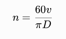
At \(v=20\) m/s and \(D=0.40\) m, \(n\) is approximately 955 rpm. With the same surface speed and \(D=0.20\) m, \(n\)becomes approximately 1,910 rpm. These are illustrative calculations, not limits for a particular stand.
Use the diameter relevant to the operating condition and convert the result into the actual bearing speed. Then examine bearing size, heat generation, lubricant delivery and the approved cage execution. “Finishing stand” is not enough information to declare brass or steel preferable.
Four rows do not guarantee four equal shares of load
Dividing total radial load by four assumes equal row loading. Equilibrium alone does not establish that condition. The relative stiffness and displacement of the roll, bearing rings and support determine the distribution.
This is why the chock and roll neck belong in the investigation. A calculation based on ideal supports may fail to represent an assembly with taper, ovality, deformation or misalignment. Ask whether the observed contact patterns agree with the assumed distribution before attributing distress to cage material.
RKB’s mounting guidance describes a long/short roller arrangement intended to improve load distribution and reduce edge pressure. It requires dimensional checks of the roll neck and chock in several planes and directions. Its GX configuration also controls roller drop and modifies the inner-ring entry geometry to reduce damage during mounting. These are examples of geometry and handling decisions influencing reliability. rkbbearings.com
During a failure review, compare the four rows individually: distress location, contact pattern, roller condition and cage-pocket damage. Inspect the lubricant route, evidence of coolant entry, sealing condition, cooling conditions, fits and assembly sequence. Determine whether damage originated during operation or during a roll change. These observations help distinguish a cage limitation from a wider installation problem.
For a critical mill stand, I would consider a machined-steel, pin or stud execution where its validated strength and roller arrangement meet severe duty. I would retain or select an approved brass construction where its guidance, lubrication and handling features suit the stand. In both cases, the approval should cover the complete bearing and support arrangement, including the separate provision for roll thrust.
10. Angular contact ball bearings in centrifugal pumps
For a critical centrifugal pump, I would often favour a manufacturer’s proven machined-brass angular contact bearing design when the duty justifies it. My specification would still identify the complete bearing, its pairing, clearance or preload, accuracy, lubrication and permitted operating envelope. Writing only “brass cage required” leaves too many decisions unresolved.
SKF recommends its machined-brass M cage for harsh, heavy-duty centrifugal-pump service, including refinery pumps. NSK’s BMPC pump bearing similarly combines machined brass with a 40° contact angle, P6 accuracy and a controlled axial-clearance range intended to help prevent skidding. These are manufacturer recommendations for particular designs. Follow the applicable pump specification and contracted standard edition; this is not a claim that API 610 universally prohibits steel cages. cdn.skfmediahub.skf.com
First, recognise where steel remains appropriate
SKF describes ordinary double-row angular contact bearings with pressed-steel cages as widely used in medium-duty centrifugal pumps. It separately describes split-inner-ring versions with 40° contact angles and machined-brass cages. Changing between these designs changes more than cage material. cdn.skfmediahub.skf.com
Consequently, a successful water-service or process-pump bearing does not need replacement simply because its cage is steel. Ask what operating limitation the proposed change would resolve. If the answer is only “brass looks stronger,” the engineering justification is incomplete.
A real comparison: NSK 7312 BEAMR and 7312 BEAW
The following values come from NSK’s 2025 angular contact bearing catalogue. MR identifies machined brass; W identifies pressed steel. nsk.com
| Catalogue property | 7312 BEAMR | 7312 BEAW |
|---|---|---|
| Bore × outside diameter × width | 60 × 130 × 31 mm | 60 × 130 × 31 mm |
| Dynamic load rating, C | 107 kN | 107 kN |
| Static load rating, C₀ | 68.5 kN | 68.5 kN |
| Limiting speed with grease | 4,800 rpm | 3,400 rpm |
| Limiting speed with oil | 6,700 rpm | 4,500 rpm |
The MR row carries the NSKHPS asterisk identifying P5 running accuracy and P6 dimensional accuracy; the W row does not. NSK also states that 73BEAW bearings have their own axial-clearance and preload specifications. The published brass/resin clearance table must not automatically be applied to W. nsk.com
Consider two illustrative duties using these catalogue values:
- A grease-lubricated pump at 2,950 rpm: both listed limits exceed shaft speed. That observation alone gives no reason to reject W, and it does not establish that either complete installation is acceptable.
- A grease-lubricated pump at 3,600 rpm: shaft speed exceeds the listed W grease limit, while remaining below the MR limit. A change from MR to W therefore requires resolution of a clear catalogue-speed conflict; matching dimensions are insufficient.
These are screening examples, not operating approvals. Confirm how the manufacturer’s limiting-speed values apply to the actual paired arrangement, including any required speed reduction, operating preload, lubrication and heat removal. Do not use the higher oil limit to approve a grease-lubricated machine.
The thrust bearing and the backup bearing have different problems
A pump may impose a dominant axial force in one direction. One bearing in an opposed pair then gains load while the other loses load. SKF explains that an insufficiently loaded backup bearing can develop disturbed rolling and smearing, followed by heat, surface damage or cage breakage. A brass cage does not remove the minimum-load requirement. Evolution
This creates an easily misunderstood failure story: the cage breaks, so the investigation concludes that the cage was too weak. The useful question is whether the cage was subjected to abnormal forces because the balls were already behaving incorrectly. Examine the rolling surfaces and operating history before treating the broken component as the original cause.
For a standby pump, capture low-load testing as well as production operation. A replacement selected only for the normal duty point may leave the fault-producing operating mode unexamined.
SKF describes engineered 40°/25° sets that retain more residual loading in the backup bearing than its illustrated equal-angle arrangement under dominant thrust. The smaller-angle bearing addresses load distribution; selecting brass alone would not produce that result. Evolution
Contact angle also creates a tradeoff. SKF identifies smaller angles as useful for high speed with moderate axial loads, but explains that a smaller angle produces greater ball/ring contact forces under the same pure axial load. A 25° or 15° substitution therefore needs an assessment of thrust capacity and operating geometry. Evolution
One established example is MRC PumPac: an engineered 40°/15° set with machined-brass cages. SKF requires the 40° bearing to face the principal thrust and cautions against applications with unknown thrust direction. It is not a recipe for combining arbitrary stock bearings. cdn.skfmediahub.skf.com
Pairing and mounting determine what the cage experiences
NSK distinguishes three arrangements: back-to-back supports bidirectional thrust and moments through widely separated effective load centres; face-to-face also supports bidirectional thrust, with less moment capacity; tandem shares thrust in one direction. NSK also distinguishes controlled matched sets from independently selected single bearings whose combined properties can vary. NSK Global
Specify an approved matched set or universally matchable execution at the required clearance/preload. The bearing designation, arrangement and mounting instructions should agree; a purchasing substitution must preserve all three.
SKF explains that interference fits and a hotter shaft/inner ring can reduce a pair’s initial clearance or increase preload. The cold, unmounted condition is therefore different from the operating condition. cdn.skfmediahub.skf.com
For a repeated pump failure, I would request the actual shaft and housing measurements, assembly records, endplay or preload method, operating temperatures and thrust envelope. Include startup, shutdown and operation away from the normal duty point. A request for “the same bearing with a stronger cage” should follow that assessment.
My practical choice: favour the approved machined-brass design when its demonstrated pump-duty capability is needed; retain an approved steel design when it satisfies the application. When the problem is backup-bearing unloading, incorrect pairing or excessive operating preload, correct that condition as part of the bearing decision.
11. Extend the decision to other bearing types and applications
The following is an engineering selection guide based on the mechanisms discussed above. It identifies where I would begin the assessment, rather than granting approval to an unspecified bearing.
| Application or bearing type | Practical starting position | What could change the decision? |
|---|---|---|
| General deep-groove ball bearings in motors, conveyors and auxiliary equipment | Retain an approved pressed-steel execution when its ratings and operating record satisfy the duty. | A demonstrated requirement for a particular high-speed, large-bearing or severe-duty execution. |
| Oil-lubricated industrial gearboxes | Compare the complete brass and steel designs offered for the actual bearing position. | Minimum load, gear forces, reversals, guidance lubrication, oil delivery and cage dynamics. |
| Wind-turbine or other demanding generator bearings | Use the validated generator-bearing design and its specified lubrication procedure. | Evidence from the relevant generator series, including friction, grease replenishment and electrical-current control. |
| Crushers, screens and other machinery with deliberate or severe vibration | Begin with the manufacturer’s bearing execution for the specified vibration duty. | Permissible acceleration, impact spectrum, operating clearance and the bearing’s complete construction. |
| Tapered roller bearings | Select the approved cage together with the setting or preload and lubrication arrangement. | A change in speed, thrust, impact, roller-end contact conditions or temperature. |
| Needle roller bearings and thin-section arrangements | Preserve the intended cage, roller guidance and space envelope. | Replacement geometry, roller retention and supplier qualification; bulkier construction may not fit the design. |
| Thrust bearings and vertical shafts | Establish the axial load, its direction and minimum load first. | Startup, unloading, reversals and lubricant delivery to the loaded contacts. |
| Very high-speed machine-tool spindles | Assess the complete precision-bearing system, including approved nonmetallic cage options where offered. | Contact angle, preload, balance, guidance, lubricant supply and thermal growth. |
| Aerospace, cryogenic, vacuum or chemically exposed machinery | Use the application-qualified material, surface treatment and bearing assembly. | The actual environment and validation requirements dominate a general industrial cage preference. |
There is manufacturer support for resisting a blanket “critical means brass” rule. NSK describes pressed steel as usual for its general deep-groove ball bearings, with machined brass available in certain larger or higher-speed designs. SKF’s aerospace catalogue identifies steel cages as standard in many aeroengine bearings, often with silver plating to improve friction behaviour. These are demanding applications using deliberately selected steel constructions. NSK
For precision spindles, even the brass-versus-steel question can be too narrow. SKF lists phenolic resin as standard for its super-precision angular contact ball bearings and uses other materials in specific designs. The relevant comparison is between qualified precision-bearing systems. skf.com
12. Fits and operating clearance can overturn a good cage selection
Initial clearance, clearance after mounting and clearance while running are different quantities. NSK explains that interference fits and unequal ring temperatures change the clearance, and that C3 is a larger initial-clearance class than CN. C3 is not a cage material or a universal reliability upgrade. NSK Global
As a simplified bookkeeping example, assume a radial bearing starts with 65 μm clearance, mounting consumes 25 μm and the thermal condition consumes another 25 μm. The estimated remaining clearance is 15 μm. If the thermal reduction becomes 40 μm, the same arithmetic gives zero.
These assumed numbers are not a fit recommendation or a complete elastic bearing calculation. They demonstrate why a seemingly small change in fit or temperature can be more consequential than cage metal. Actual assessment must use the bearing manufacturer’s method and dimensional tolerances.
When reviewing a substitution, record the original and replacement clearance classes, actual measured fits and expected temperature difference. For angular contact pairs, assess operating preload or endplay using the appropriate pair method; do not transfer a radial-clearance calculation to that arrangement.
Keep alignment and thermal displacement in the same review. A rigid coupling, an overhung load or an incorrectly constrained floating position can change the load distribution. A stronger cage should not be used to justify an installation condition outside the bearing’s approved envelope.
13. Diagnose the failure before naming the replacement cage
A broken cage identifies a damaged component. It does not, by itself, establish the first failure mechanism.
NSK’s damage examples include fractures and wear in brass cages, fractures in pressed-steel cages and mounting damage in both constructions. Its guidance points to lubrication, alignment, dynamic loads and handling as possible contributors. NSK Americas
I would use the evidence to frame the investigation:
| Observation | Questions to resolve before selecting another cage |
|---|---|
| Cracked cage bars, loose joints or deformed pockets | Was there fatigue, a single impact, severe acceleration or handling damage? Where did the crack start? |
| Heavy wear at pockets or guiding surfaces | Did lubricant reach those contacts? Were the guidance clearances and rolling-element motion satisfactory? |
| Smearing or distress on rollers and raceways | Was the bearing sufficiently loaded through the full operating cycle? What were viscosity and startup conditions? |
| Damage concentrated in one row or one region | Does the contact pattern agree with the assumed loads, alignment, fits and support stiffness? |
| Debris, staining or chemical attack | What entered the lubricant, and which materials and surfaces were exposed? |
These observations generate hypotheses; they are not unique diagnoses from a photograph.
Use oil and grease analysis carefully
Copper-containing debris is a reason to investigate a brass cage when one is installed. It is not proof that the cage is the source if the system contains other copper-alloy components. Compare the actual cage alloy, other exposed components, lubricant baseline and particle composition.
A magnetic debris indication and an elemental oil result answer different questions. WearCheck distinguishes ferrous-debris measurement from microscopic examination of particle shape and composition, and explains why wear-particle analysis can reveal information absent from ordinary ppm trends. Select methods that can examine the material you suspect. Wear Particle Analysis
Preserve representative grease, oil, filter debris and the damaged bearing before cleaning destroys useful evidence. Record operating hours, starts, load changes, temperatures, vibration and lubrication events. Where the cause remains uncertain, examination of fracture surfaces and particle composition can be more useful than another unstructured trial.
Compare replacements under comparable conditions
A new brass bearing may run cooler after a repair that also corrects fits, cleans the housing, changes the grease and restores the floating position. That is evidence of a successful repair package. It does not isolate the effect of cage metal.
To assess a cage-related change, document all simultaneous changes and compare operation at comparable speed, load and thermal conditions. Establish acceptance criteria before commissioning: temperature behaviour, vibration, lubricant condition, operation through the relevant duty cycle and a suitable inspection or service interval.
Do not deliberately preserve a known damaging condition merely to obtain a cleaner comparison. Correct the machine and be honest about what the evidence can establish.
14. Write a bearing specification that can be purchased and verified
For a critical replacement, I would require the following information in the technical selection record:
- The exact bearing: manufacturer, complete designation, internal execution and approved alternatives.
- Cage construction: pressed, machined, pin or stud; material; guidance; and relevant surface treatment.
- Loads: radial and axial loads, their direction, maximum events, minimum-load conditions and the start/stop spectrum.
- Speed: continuous, transient and maximum speed, with the correct lubrication assumptions behind the permitted values.
- Lubrication: finished lubricant, operating viscosity, quantity or flow, delivery route, replenishment, drainage and cleanliness requirements.
- Mounting and temperature: fits, alignment, initial and operating clearance or preload, and provision for relative axial movement.
- Evidence and acceptance: manufacturer suitability confirmation, relevant operating history and the checks needed to establish satisfactory operation.
Then state the reason for the cage choice in one concrete sentence. For example:
Use this approved brass execution because the required grease-speed envelope exceeds that of the offered steel alternative.
Or:
Retain this approved steel execution because it satisfies the complete duty and the proposed brass substitution provides no demonstrated operating advantage.
Avoid procurement instructions such as “same size, brass preferred” when a change can also alter guidance, precision, clearances or pairing. A full designation is necessary, and its technical meaning still needs checking against the manufacturer’s current data.
Once both alternatives satisfy the duty, compare purchase price, lead time, interchangeability, maintenance requirements and expected outage consequences. A higher purchase price is justified by a demonstrated benefit; price alone does not prove or disprove that benefit.
15. Finally: brass cage or steel cage?
For an ordinary, properly loaded NU motor bearing with stable operation and an approved steel design, I would retain steel unless a specific duty requirement supports changing it. For severe motor dynamics, I would give a validated robust brass construction serious preference where the manufacturer has developed it for that duty. I would first correct underloading, poor lubrication, restricted expansion or electrical damage if any of those is the actual problem.
For spherical roller bearings in fans, I would select the execution that best satisfies the real load, speed and thermal conditions. Engineered steel is a strong candidate for continuous service. A proven brass design can be appropriate for demanding transients. The assessment must include both roller rows and the shaft’s ability to expand.
For four-row CRBs in rolling mills, I would treat machined steel, steel pin or stud designs, and machined brass as distinct application solutions. Severe reversing duty can justify a strong steel architecture; approved brass designs remain valid for other mill requirements. Roller construction, chock condition, lubrication and handling may decide the result.
For severe-duty centrifugal-pump angular contact bearings, I would generally start with the manufacturer’s established machined-brass pump design. Approved steel designs remain appropriate where their application envelope is sufficient. Contact angle, matching, backup-bearing loading and operating preload are essential parts of that choice.
The engineering conclusion is precise: choose the cage whose complete bearing design has a demonstrated advantage under the machine’s actual conditions. Criticality raises the standard of evidence required for selection; it does not assign a winning metal.
Khash, MLE, CLS, MLA III, MLT II, VIM, VPR

