I have seen in my career many ID fan bearings in Cement industry failing due to the current from the VFD motor passing through the coupling and causing fluting in the fan bearings.
So wrote below detailed article about it.
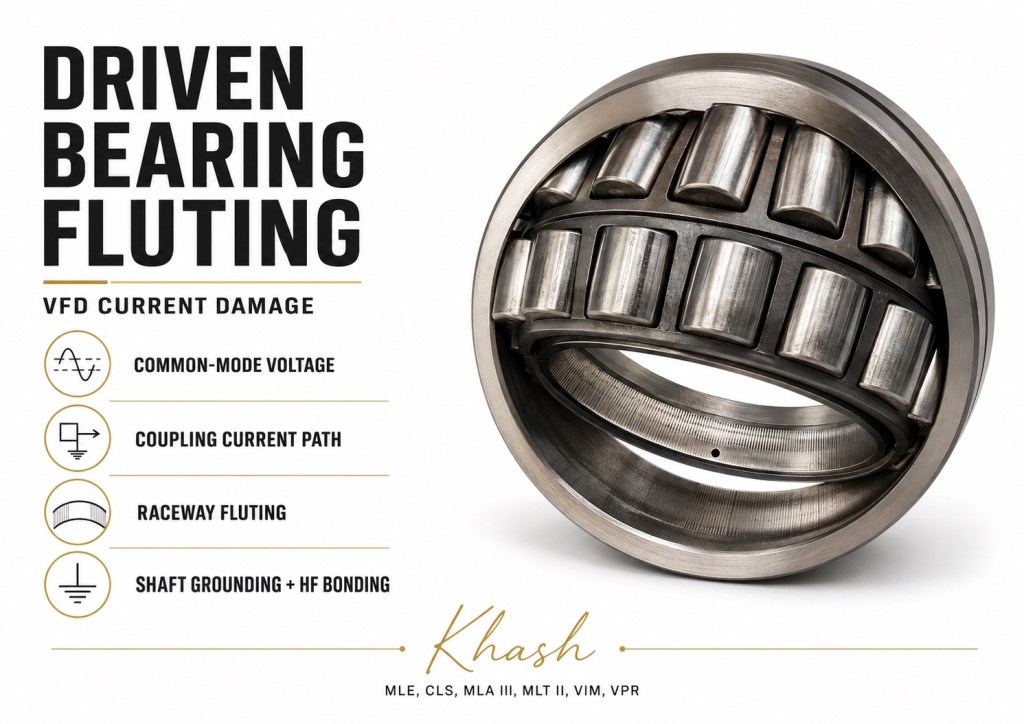
Fluting of Driven Equipment Bearings Connected to VFD Motors
1. The key point
When a motor is supplied by a VFD, the problem is not always limited to the motor bearings. The current can travel through the motor shaft, coupling, gearbox, pump, fan, roll, compressor, or other driven equipment, then discharge through the driven machine’s bearings.
So the driven bearing can fail even when:
- the driven equipment has no electrical power of its own,
- the motor bearings look better than the load bearings,
- the motor has insulated bearings,
- the motor is called “inverter duty.”
NEMA specifically warns that insulating motor bearings does not automatically prevent damage to other shaft-connected equipment. It also notes that inverter-driven systems can produce high-frequency shaft-to-ground voltage pulses that may drive destructive bearing currents.
2. What fluting is
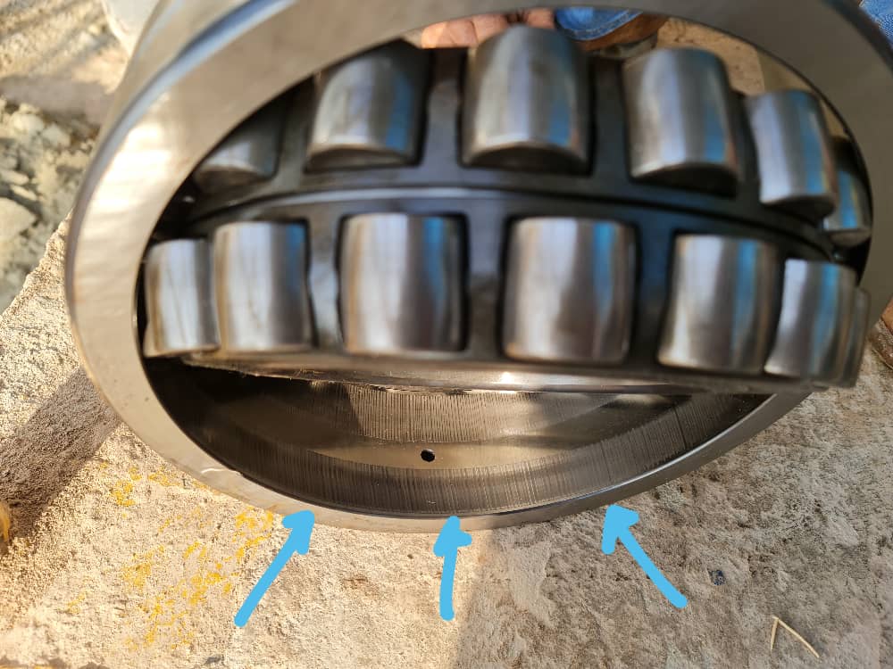
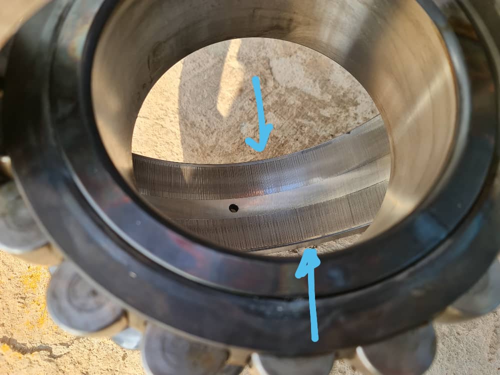
Fluting is the visible washboard pattern that develops on the raceway after electrical discharge damage has been occurring for some time.
The actual first damage is usually EDM microcratering. Tiny electrical arcs pass through the lubricant film between rolling element and raceway. Each arc creates a small molten pit. Over time, thousands or millions of pits roughen the surface. As the rollers continue to pass over that damaged surface, a regular ribbed or washboard pattern develops. SKF describes fluting as a pattern of multiple grey lines across the raceway and notes that it is secondary damage that develops from microcraters over time.
A practical way to say it:
Microcratering is the electrical attack. Fluting is the mechanical pattern that follows.
3. Why VFDs create the problem
A normal three-phase sine wave supply is balanced. Ideally, the sum of the three phase voltages is zero at every instant.
A PWM VFD is different. The drive rapidly switches DC bus voltage into pulses. At any instant, the three output voltages do not sum to zero. This creates common-mode voltage:
That common-mode voltage changes very quickly because of the VFD’s switching edges. The faster the voltage changes, the more high-frequency leakage current is forced through parasitic capacitances in the motor, cable, frame, rotor, bearings, and driven machine.
A simplified expression is:
Where:
| Term | Meaning |
|---|---|
| I | high-frequency leakage current |
| C | stray capacitance |
| dV/dt | voltage rise rate from the VFD switching pulses |
ABB explains that high-frequency bearing currents are linked to the common-mode circuit of AC drive systems, and that fast VFD switching, grounding, cabling, and motor/frame/shaft grounding strongly influence the bearing current level.
4. How the current reaches the driven equipment
This is the important part for your case.
A VFD creates common-mode current. That current wants to return to the inverter. It will use the lowest impedance path, not necessarily the path we want.
In a real plant, the return path can include:
- motor frame,
- motor bearings,
- motor shaft,
- metallic coupling,
- gearbox shaft,
- pump shaft,
- fan shaft,
- roll shaft,
- driven equipment bearings,
- baseplate,
- foundation,
- structural steel,
- cable shield,
- PE/earth conductor,
- VFD frame.
ABB specifically describes a case where, if the motor shaft is connected through a metallic coupling to a gearbox or other driven machinery, part of the inverter common-mode current can flow through the motor bearings, shaft, and driven machinery back to the inverter. It also states that if the driven machinery shaft has no direct contact to ground, current may flow through gearbox or machine bearings, and those bearings may be damaged before the motor bearings.
That is exactly why driven equipment bearings can show fluting.
5. Common current path in driven equipment
A typical damaging path is:
VFD → motor cable → motor winding capacitance → rotor/shaft → coupling → driven shaft → driven bearing → driven housing/base → plant ground → VFD
Or:
VFD → motor frame voltage rise → motor DE bearing → shaft → coupling → driven bearing → driven machine frame → earth
This second case is common when the driven machine has a better ground than the motor. The current “chooses” the driven equipment because it offers a better high-frequency return path.
6. Why motor bearing protection can move the problem to the driven machine
This is a major trap.
A repair shop may install insulated motor bearings and think the issue is solved. But if the motor shaft voltage is still present, and there is a metallic coupling to the driven equipment, the voltage may discharge through the pump bearing, fan bearing, gearbox bearing, roll bearing, or compressor bearing instead.
So the motor survives, but the driven equipment fails.
That is why bearing-current mitigation must be done at the system level, not just at the motor.
7. How the damage appears
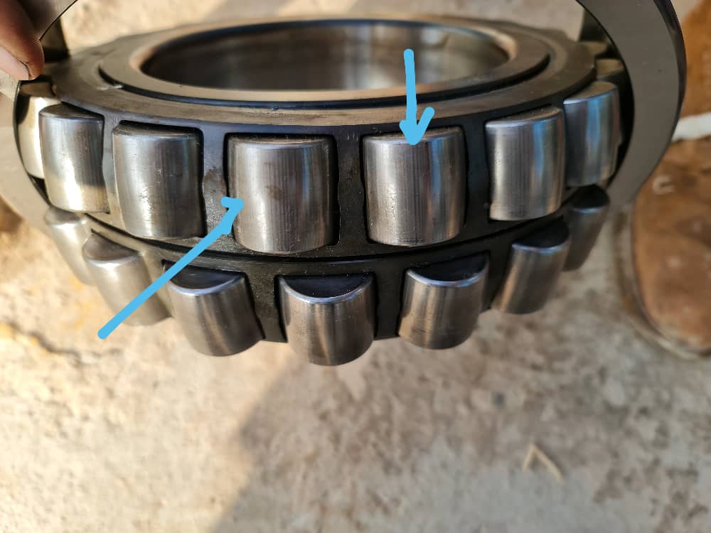
Typical electrical fluting symptoms:
| Component | Typical appearance |
|---|---|
| Raceway | Fine parallel washboard grooves |
| Rolling elements | Dull grey, frosted, or streaked surface |
| Grease | Black, burnt, carbonized, dry, or hard |
| Bearing noise | Whining, growling, rumbling |
| Vibration | Bearing defect frequencies plus broadband high-frequency energy |
| Microscopy | Tiny electrical craters, often only visible under magnification |
SKF notes that electrical current passage can produce dull grey surfaces, microcraters, fluting/washboarding, lubricant degradation, black hard grease, and later secondary surface distress or spalling.
In your photos, the fine repetitive raceway lines and dull roller tracks are much more consistent with electrical erosion/fluting than with simple contamination scratching.
8. Why driven equipment bearings often fail first
Driven equipment bearings can fail first for several reasons:
| Reason | Explanation |
|---|---|
| Better ground path | Pump or gearbox may be better grounded than the motor |
| Metallic coupling | Provides direct electrical path from motor shaft to driven shaft |
| Insulated motor bearing | Blocks motor bearing path, pushing current to load side |
| Poor VFD cable shielding | Common-mode current searches for other return paths |
| Rubber pads or painted bases | Increase impedance of normal grounding path |
| Long motor cable | Increases parasitic capacitance and high-frequency effects |
| Poor bonding across baseplate | Motor and driven machine sit at different high-frequency potentials |
| No shaft grounding | Shaft voltage has no safe discharge path |
At high frequency, a normal green/yellow earth wire may be a poor path because inductance becomes important. The current may prefer a wide metal structure, a coupling, or a bearing path instead.
9. The three main VFD bearing-current mechanisms
A. Capacitive discharge current
The VFD common-mode voltage capacitively couples from stator winding to rotor. The rotor and shaft charge up. When shaft voltage exceeds the dielectric strength of the lubricant film, the bearing discharges like a tiny spark gap.
This creates EDM pits.
This can happen in motor bearings or, through a coupling, in driven equipment bearings.
B. Shaft grounding current
The motor frame can rise in potential relative to the drive or plant ground because the high-frequency common-mode current sees impedance in the PE path. If the driven machine is better grounded, current may pass from motor frame through motor bearing, shaft, coupling, driven machine, and back to the inverter.
This is a very important driven-equipment failure mode.
C. High-frequency circulating current
In larger motors, common-mode current can create high-frequency magnetic effects that induce shaft voltage from one shaft end to the other. ABB describes internal circulating bearing currents and also an external “vagabond” circulating current where the current loop goes through the shaft, gearbox or driven machinery bearings, and common structural elements outside the motor.
10. Why the lubricant does not protect the bearing
The oil or grease film normally separates the rolling elements and raceway mechanically. Electrically, that same lubricant film behaves like a dielectric.
At first, it blocks current. Then voltage builds. When the voltage becomes high enough, the film breaks down and a discharge occurs.
That discharge is extremely local. It can melt or vaporize a microscopic spot on the raceway. One discharge is small. Repeated discharges create thousands of craters. Then the rollers mechanically hammer and polish those craters into fluting.
ABB notes that bearing voltage can short-circuit when it exceeds the oil film breakover value or when surface contact breaks through the film, and that bearing impedance changes with load, temperature, speed, and lubricant.
11. Why it is worse with long VFD cables
Long motor leads increase parasitic capacitance between phase conductors, shield, conduit, ground, motor frame, and surrounding structure. More capacitance means more common-mode leakage current.
Long cables can also increase reflected-wave and high dV/dt stress at the motor terminals. This is why a system that works with a short cable may develop bearing current problems after relocation, extension, or cable replacement.
12. Why grounding alone often fails
Standard grounding is mainly designed for safety at power frequency. Bearing currents from VFDs are high-frequency phenomena.
At high frequency, impedance is not just resistance:
A round earth cable may have low DC resistance but high inductance at high frequency. That makes it less effective for VFD common-mode current.
That is why wide, short bonding straps are better than long round wires for high-frequency bonding. ABB recommends low-impedance paths, continuous shields, 360° terminations, and flat copper bonding straps to equalize potential between the motor and driven machinery.
13. Practical root-cause signs
Suspect VFD-related driven-equipment fluting when you see:
- fluting on pump/gearbox/fan bearings,
- motor is VFD-driven,
- metallic coupling between motor and driven machine,
- failure repeats after normal mechanical corrections,
- grease turns black or hard,
- bearing noise returns quickly after replacement,
- motor has insulated bearings but load bearings fail,
- motor and driven equipment have different grounding quality,
- long motor cable or poor shield termination,
- no shaft grounding ring or brush,
- damage appears on multiple bearings in the shaft train.
14. How to confirm the diagnosis
A. Bearing inspection
Inspect for:
- fine washboard grooves,
- frosted grey raceway,
- blackened grease,
- matching damage on rolling elements,
- microcraters under microscope,
- damage on both motor and driven equipment bearings.
Do not rely only on the naked eye. Early electrical erosion can look like polishing or grey staining.
B. Electrical inspection
Check:
- motor cable type,
- shield continuity,
- shield termination method,
- VFD grounding,
- motor frame bonding,
- driven machine bonding,
- baseplate paint/rust,
- flexible coupling type,
- insulated bearings,
- shaft grounding device condition,
- output filters or lack of filters.
C. Shaft voltage/current measurement
Use an oscilloscope and proper shaft voltage probe or brush contact. Measure:
- motor shaft to motor frame,
- motor shaft to driven machine frame,
- driven shaft to driven machine frame,
- shaft voltage before and after grounding device,
- high-frequency current in bonding straps and grounding paths.
ABB notes that suspected high-frequency bearing current measurements require wide-band equipment and experienced personnel, because the current may flow in unusual places such as rotating shafts.
This should be done only by qualified personnel using safe electrical procedures.
15. How to stop it — practical solutions
Solution 1: Treat motor + driven machine as one electrical system
Do not protect only the motor.
The system includes:
VFD + cable + motor + coupling + driven shaft + driven bearings + baseplate + grounding network
If you ignore the driven equipment, the current may simply move from one bearing to another.
Solution 2: Install proper shaft grounding
A shaft grounding ring or brush gives the shaft current a preferred path that bypasses the bearings.
For driven equipment protection, the grounding device should normally be placed so the current is removed before it reaches the coupling and driven machine.
Good practice:
| Point | Recommendation |
|---|---|
| Location | Often near the drive end/coupling side of the motor |
| Connection | Very short, low-impedance connection to motor frame |
| Contact surface | Clean bare shaft, no paint, rust, oil film, or heavy contamination |
| Maintenance | Inspect brush/ring contact regularly |
| Large motors | May need shaft grounding plus insulated bearing strategy |
| Coupled equipment | Consider shaft grounding on motor and sometimes on driven shaft |
Important: if both motor bearings are insulated, the shaft must not be left floating. Provide a controlled shaft grounding path.
Solution 3: Use insulated bearings correctly
Insulated bearings break a current path. They do not remove the shaft voltage.
Possible options:
| Option | Use |
|---|---|
| Insulated NDE motor bearing | Common for interrupting circulating current in many larger motors |
| Insulated DE and NDE motor bearings | May be needed for some discharge-current cases, but shaft grounding is usually required |
| Hybrid ceramic rolling element bearings | Strong electrical insulation and good high-speed capability |
| Insulated driven equipment bearing | Useful if current is confirmed through driven machine bearing |
| Insulated bearing housing/sleeve | Can break housing-to-shaft path |
SKF lists insulated bearings and hybrid bearings as solutions for electrical erosion; hybrid bearings use silicon nitride rolling elements, which electrically insulate the shaft from the housing.
But do not randomly insulate one bearing without understanding the full current path. Insulation can move the discharge to the next available component: another bearing, coupling, seal, gear mesh, encoder, tachometer, or process equipment.
Solution 4: Use an insulated coupling when needed
An insulated coupling can prevent motor shaft voltage from entering the driven machine.
This is especially useful when:
- driven equipment bearings are repeatedly fluting,
- motor bearings are insulated,
- a metallic coupling is providing the current path,
- the driven machine is very well grounded,
- the load is expensive or difficult to repair.
But an insulated coupling should not be installed alone. If the motor shaft voltage is blocked from going into the driven machine, it still needs a safe path. Usually that means:
insulated coupling + motor shaft grounding + correct motor bearing insulation
NEMA also notes that when a motor has insulated bearing protection, an insulated coupling or other means may be needed to prevent shaft potentials from being applied to connected accessories.
Solution 5: Bond motor and driven equipment frames together
Install high-frequency bonding straps between:
- motor frame and baseplate,
- driven machine frame and baseplate,
- motor frame and driven machine frame,
- gearbox and motor frame,
- pump/fan frame and motor frame,
- skid/base and plant ground.
Use short, wide, flat braided copper straps. Do not rely only on:
- foundation bolts,
- rusty shims,
- painted feet,
- flexible rubber pads,
- long round earth wires,
- conduit threads,
- random structural steel.
ABB specifically recommends high-frequency bonding between motor and driven machinery to short the current path through motor and driven machine bearings.
Solution 6: Correct the VFD motor cable installation
Use proper VFD cable practice:
- symmetrical three-phase motor cable,
- symmetrical protective earth arrangement,
- continuous copper/aluminium shield or armour,
- 360° shield termination at both VFD and motor ends,
- no long pigtail shield connections,
- short low-impedance PE path,
- separate motor cables from sensitive instrumentation,
- avoid unnecessarily long cable runs.
ABB states that proper high-frequency grounding relies on symmetrical multicore motor cables, continuous shielded motor cables, and 360° terminations.
Solution 7: Add common-mode filters or chokes
A common-mode filter/choke reduces the high-frequency common-mode current leaving the drive.
This is one of the strongest system-level solutions when:
- motor cable is long,
- several bearings show electrical damage,
- grounding is already improved but problem remains,
- large motors are involved,
- driven equipment bearings are being damaged.
Do not confuse all filter types:
| Device | Main effect |
|---|---|
| Output reactor | Reduces some current ripple and edge stress, limited common-mode effect |
| dV/dt filter | Reduces voltage rise rate and reflected-wave stress |
| Sine-wave filter | Produces near-sinusoidal motor voltage, reduces high-frequency stress strongly |
| Common-mode choke/filter | Specifically reduces common-mode current |
ABB identifies three broad prevention approaches: proper cabling/earthing, breaking bearing current loops, and damping the high-frequency common-mode current with filters.
Solution 8: Reduce carrier frequency where acceptable
Lower carrier frequency can reduce the number of switching events and sometimes reduce bearing-current activity. But it may increase audible motor noise, torque ripple, or heating. This should be done with the VFD and motor manufacturer’s guidance.
This is a supporting correction, not a complete fix by itself.
Solution 9: Replace damaged bearings after correction
Once fluting is visible, the raceway is already damaged. Regreasing may reduce noise temporarily, but it cannot remove the craters or washboard pattern.
Correct sequence:
- Confirm electrical erosion.
- Correct shaft current path.
- Install grounding/bonding/filter/insulation solution.
- Replace damaged bearings.
- Flush contaminated grease or oil.
- Run and remeasure shaft voltage/current.
- Trend vibration.
If you only replace the bearing, the new bearing may fail again.
16. Solution combinations by situation
Case A: Motor bearings and driven bearings both fluted
Recommended package:
- shaft grounding ring/brush on motor,
- high-frequency bonding motor-to-driven machine,
- proper shielded VFD cable with 360° terminations,
- inspect grounding back to VFD,
- consider common-mode filter,
- replace damaged bearings.
Case B: Motor has insulated bearings, but pump/gearbox bearing is fluted
Likely problem:
The motor bearing path was blocked, so current went through the coupling into the driven machine.
Recommended package:
- install motor shaft grounding near coupling side,
- add HF bonding between motor and driven frame,
- consider insulated coupling,
- consider driven equipment insulated/hybrid bearing if current persists,
- verify with shaft voltage measurement.
Case C: Large motor driving gearbox
Likely risks:
- circulating current,
- external “vagabond” current through gearbox bearings,
- gear mesh discharge,
- bearing and seal damage.
Recommended package:
- insulated NDE motor bearing or OEM-recommended insulated bearing arrangement,
- shaft grounding,
- common-mode filter,
- HF bonding motor/gearbox/base,
- possible insulated coupling,
- inspect gearbox bearings and oil for electrical damage debris.
Case D: Long cable VFD pump or fan
Likely risks:
- high common-mode current,
- reflected wave,
- shaft voltage discharge,
- driven bearing fluting.
Recommended package:
- VFD-rated shielded cable,
- 360° shield terminations,
- output dV/dt or sine filter if cable is long,
- common-mode choke if bearing current persists,
- shaft grounding,
- motor-to-load bonding.
17. Common mistakes
| Mistake | Why it fails |
|---|---|
| Installing only insulated motor bearings | Can move current to driven equipment |
| Installing only an insulated coupling | Can make motor shaft voltage discharge through motor bearings |
| Using only a long round ground wire | Too much high-frequency impedance |
| Leaving paint under bonding straps | Poor electrical contact |
| Grounding only for 50/60 Hz safety | Bearing currents are high-frequency |
| Regreasing a fluted bearing | Does not repair craters |
| Replacing bearings without electrical correction | Failure repeats |
| Assuming “inverter duty” means bearing-current protected | Not always true |
| Installing shaft ring on dirty/painted shaft | Poor contact, no protection |
| Using output reactor and assuming problem solved | May not sufficiently reduce common-mode current |
18. Practical corrective action plan
For your type of case, I would use this order:
Step 1 — Confirm the failure mode
Inspect bearing raceway, rollers, and grease. Look for:
- washboard lines,
- grey frosting,
- microcraters,
- black grease,
- repeated failure history.
Step 2 — Map the electrical path
Draw the actual path:
VFD → cable → motor → coupling → driven equipment → base → earth → VFD
Mark all possible current crossings:
- motor DE bearing,
- motor NDE bearing,
- coupling,
- gearbox input bearing,
- pump bearing,
- fan bearing,
- seal,
- encoder bearing,
- baseplate.
Step 3 — Measure shaft voltage
Measure:
- motor shaft to motor frame,
- driven shaft to driven frame,
- motor frame to driven frame,
- motor frame to VFD ground,
- bonding strap current if possible.
Step 4 — Add a safe discharge path
Install shaft grounding so current bypasses bearings.
Step 5 — Improve high-frequency bonding
Bond motor and driven frame with wide braid.
Step 6 — Correct VFD cabling
Use shielded symmetrical cable and 360° terminations.
Step 7 — Add filtering if needed
Use common-mode filter/choke, dV/dt filter, or sine filter depending on the system.
Step 8 — Insulate strategically
Use insulated bearings or insulated coupling only after identifying where the current is flowing.
Step 9 — Replace damaged bearings
Do this after mitigation, not before.
19. Strong report wording
You can write it like this:
The bearing damage is consistent with electrical erosion/fluting. The raceway shows fine repetitive washboard marks and the rolling elements show dull grey electrical tracking. In a VFD-driven motor system, common-mode voltage can capacitively couple to the motor rotor and shaft. If the shaft is connected through a metallic coupling to driven equipment, high-frequency current may discharge through the driven equipment bearings. The damage should be treated as a system grounding, bonding, shaft-voltage, and common-mode current issue, not as a bearing-quality issue. Corrective action should include shaft grounding, high-frequency bonding between motor and driven equipment, proper shielded VFD cabling with 360° terminations, and, where required, common-mode filtering, insulated coupling, or insulated/hybrid bearings.
20. Main takeaway
For driven equipment connected to VFD motors:
The bearing that fails is not always the bearing where the voltage is created.
The VFD creates the common-mode voltage in the motor system, but the current may discharge through the driven equipment bearing if that is the easiest path back to ground.
The best solution is usually not one item. It is a package:
shaft grounding + HF bonding + correct VFD cable/shielding + common-mode filtering when needed + correctly placed insulation.
