One Mining Site Manager sent me below photos of a failed gearbox bearing failure of a very critical application for his process and he sent me Khash, I have never such bearing failure, what has happened ?
Below is how Khash replied Back.
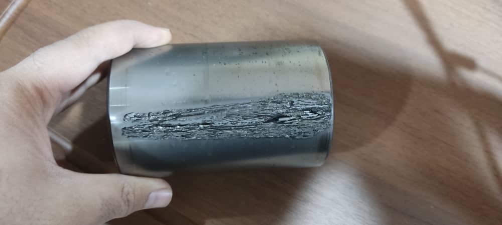
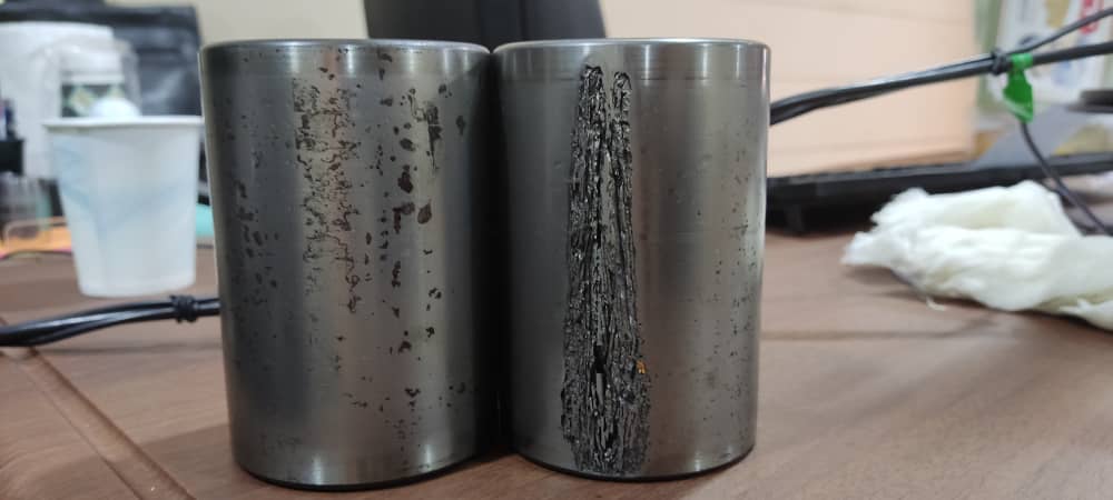
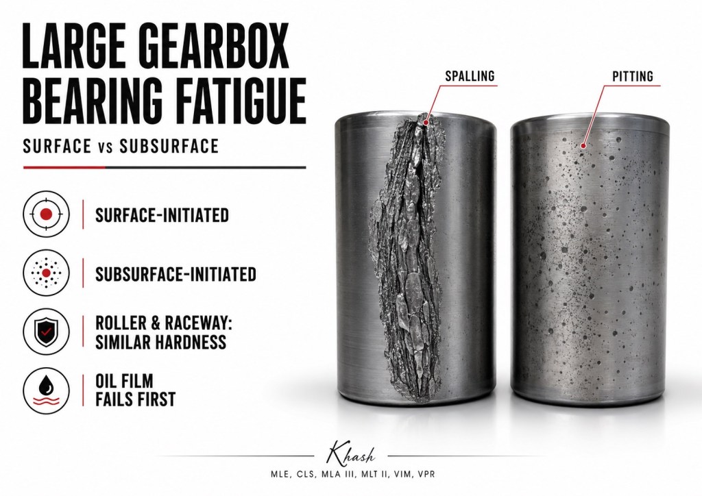
From the photos, the damaged part appears to be a large gearbox bearing roller, not a raceway ring. The damage is severe: one roller shows a long, rough, dark, torn spall/peeling zone along the rolling surface, while the other roller shows scattered dark pits/etching. For a mining gearbox, this visual pattern is more consistent with advanced surface-origin distress progressing into spalling than with clean classical subsurface fatigue. A final diagnosis needs the matching raceways, oil analysis, and metallurgical sectioning.
Large Gearbox Bearing Fatigue
Subsurface initiated fatigue vs surface initiated fatigue, roller/raceway hardness, and failure interpretation
1. What the photos show
The attached rollers show three important clues:
- Severe local material detachment on one roller.
The damaged strip is rough, torn, dark, and irregular. This is not normal polishing or simple running-in. - Pitting/etching on the other roller.
The scattered dark spots suggest corrosion, contamination indentation, electrical/chemical attack, or oil degradation effects. In a mining gearbox, water and hard dust contamination are common suspects. - Localized damage rather than uniform fatigue.
If the bearing failed only from clean, ideal rolling contact fatigue, the surrounding surfaces would often look cleaner in the early stage. Here, the surface condition around the damage suggests a hostile lubrication environment.
My practical interpretation:
The roller damage is highly compatible with surface initiated fatigue / surface distress, probably accelerated by contaminated or degraded gearbox oil, water ingress, poor oil film thickness, hard debris, overload, edge loading, or a combination of these. It is less typical of pure classical subsurface fatigue, although subsurface fatigue cannot be ruled out without sectioning.
2. Why large gearbox bearings fail differently
Large mining gearbox bearings work under severe conditions:
- high radial load,
- shock load,
- slow-to-medium speed,
- high torque,
- gear mesh vibration,
- shaft deflection,
- housing distortion,
- oil contamination,
- water ingress,
- hard metallic debris,
- abrasive mining dust,
- thermal cycling,
- possible misalignment.
In theory, a bearing is designed for rolling contact fatigue life. In practice, many large industrial bearing failures are not “pure life failures.” They are caused by the operating environment damaging the rolling surfaces first. Schaeffler’s rolling bearing damage guide states that classical fatigue with cracks starting below the surface seldom occurs compared with fatigue that starts at the surface because of inadequate lubrication or cleanliness. (Schaeffler)
That point is very important for mining gearboxes:
Most large gearbox bearing failures are not because the bearing was too weak on paper. They are because the contact surface was damaged before the calculated fatigue life could be reached.
3. The rolling contact zone
In a roller bearing, the load is carried through a very small contact zone between the roller and the raceway. In cylindrical, tapered, and spherical roller bearings, this is approximately a line contact, not a point contact.
The simplified contact condition is:

Where:
| Term | Meaning |
|---|---|
| (Q) | load carried by one roller |
| (p_{max}) | maximum Hertzian contact pressure |
| (L_e) | effective roller contact length |
| (E’) | reduced elastic modulus |
| (R’) | reduced radius of curvature |
The steel may be very hard, but the contact pressure is extremely high. If the oil film is healthy, the surfaces survive. If the oil film fails, asperities, dents, debris, and microcracks begin to control the life.
4. Subsurface initiated fatigue
Definition
Subsurface initiated fatigue starts below the rolling surface. The maximum cyclic shear stress occurs beneath the surface, and microcracks start inside the steel. ISO 15243 describes it as microcrack initiation below the raceway surface under cyclic Hertzian loading, with initiation depth depending on load, temperature, steel cleanliness, material, and microstructure; inclusions in the bearing steel are often involved.
How it develops
The typical sequence is:
- The bearing operates under repeated Hertzian stress.
- Stress cycles occur below the surface.
- A crack starts at a weak point, often a non-metallic inclusion or microstructural discontinuity.
- The crack grows under repeated stress.
- The crack reaches the surface.
- A relatively deep spall forms.
Typical appearance
Subsurface fatigue often shows:
| Feature | Appearance |
|---|---|
| Origin | Below the surface |
| Early surface | Often looks normal before spalling |
| Spall depth | Usually deeper than micropitting |
| Damage edge | Can be sharp and shell-like |
| Surrounding surface | May look clean in early stage |
| Metallurgy | Subsurface cracks, butterflies, inclusion-related cracking, or structural change |
Common causes
Subsurface initiated fatigue is associated with:
- very high load,
- overload,
- excessive preload,
- wrong bearing size,
- poor load distribution,
- material weakness,
- inclusion-related crack initiation,
- insufficient case depth in case-hardened components,
- misalignment causing local stress concentration,
- excessive contact pressure.
Timken’s damage reference notes that heavy preload or heavy load can cause premature subsurface fatigue spalling even when the lubricant itself is able to carry the load without visible scoring. (assets.wellertruck.com)
Practical meaning
Subsurface fatigue is closer to a stress-volume problem.
The surface may be well lubricated, but the steel below the surface is cyclically overstressed until it cracks.
5. Surface initiated fatigue
Definition
Surface initiated fatigue starts at the rolling contact surface. ISO 15243 describes it as fatigue typically caused by surface distress, with asperity contact often resulting from insufficient lubricant film thickness, wrong lubricant, high operating temperature, poor surface finish, or insufficient lubricant availability. It also notes that particles, extreme loads, and handling nicks can create indentations whose raised edges break through the oil film and initiate fatigue.
How it develops
The typical sequence is:
- Oil film becomes too thin.
- Roller and raceway asperities touch.
- Surface asperities plastically deform.
- Microcracks form at the surface.
- Microspalls appear.
- The surface becomes grey, dull, frosted, or rough.
- Microspalls join together.
- Macrospalling develops.
Surface initiated fatigue is strongly linked to mixed or boundary lubrication. SKF’s damage guide states that surface initiated fatigue generally comes from damage to rolling contact asperities, commonly caused by inadequate lubrication; it also says the risk exists when the oil film does not fully separate the rolling contact surfaces and increases with sliding.
Typical appearance
Surface initiated fatigue often shows:
| Feature | Appearance |
|---|---|
| Origin | Surface |
| Early sign | Grey staining, dullness, micropitting, peeling |
| Surface texture | Rough, frosted, etched, smeared, or pitted |
| Damage depth | Starts shallow, then grows |
| Surrounding surface | Often shows contamination, corrosion, polishing, glazing, or abrasive wear |
| Common trigger | Lubrication failure, contamination, water, sliding, debris dents |
Common causes
Surface initiated fatigue is associated with:
- low oil viscosity,
- high temperature,
- insufficient oil film,
- water contamination,
- abrasive particles,
- metallic gear debris,
- poor filtration,
- wrong oil,
- oil oxidation,
- wrong EP/AW additive chemistry for the conditions,
- misalignment,
- edge loading,
- roller skewing,
- sliding,
- smearing,
- corrosion pits,
- indentation from debris.
For mining gearbox bearings, this is often the dominant failure route.
6. Key difference: subsurface vs surface initiated fatigue
| Item | Subsurface initiated fatigue | Surface initiated fatigue |
|---|---|---|
| Crack origin | Below surface | At surface |
| Main driver | Hertzian stress, material/inclusion, overload | Lubrication failure, contamination, water, surface damage |
| Early visual signs | Surface may look clean | Dull grey, pitted, etched, polished, smeared, or rough |
| Spall type | Deeper fatigue spall | Micropitting/peeling progressing to spall |
| Common in ideal clean lubrication? | Yes, after long stress cycling | Less likely if full film and clean oil exist |
| Common in mining gearboxes? | Possible | Very common |
| Confirmation method | Metallurgical sectioning | Surface microscopy, oil evidence, surface distress pattern |
| Typical corrective action | Reduce load/stress, improve bearing selection/alignment/material | Improve oil film, cleanliness, water control, filtration, sealing, alignment |
Simple field rule:
Subsurface fatigue starts from stress inside good-looking steel. Surface fatigue starts from damaged, poorly lubricated, or contaminated steel.
7. Analysis of your damaged rollers
The roller with the long damaged strip appears to show advanced spalling/peeling. The damage is dark, rough, torn, and localized. The companion roller shows many small dark pits or etched spots.
That combination points toward this chain:
- Contaminated or degraded oil reduces film strength.
- Water, dust, or metallic debris damages the roller/raceway surfaces.
- Surface indentations, corrosion pits, or asperity distress create local stress raisers.
- Microcracks start at the surface.
- Microspalls grow and connect.
- The roller loses a larger strip of material.
- Detached bearing steel circulates in the gearbox oil.
- Secondary damage appears on other rollers and raceways.
This is strongly aligned with ISO’s description that contaminants and indentations can cause surface-origin fatigue because raised material around dents exceeds the oil film and initiates further fatigue.
Most likely primary damage mode from photos
Most likely:
Surface initiated fatigue / surface distress progressing into macrospalling.
Strong contributing suspects
- contaminated oil,
- water ingress,
- inadequate oil film thickness,
- wrong oil viscosity or high oil temperature,
- poor filtration,
- gear debris passing through bearing,
- edge loading,
- shaft/housing misalignment,
- shock loading from mining duty,
- bearing overload,
- advanced secondary damage after initial spall.
Less likely as the only root cause
Pure clean subsurface fatigue is less likely as the only explanation because the visible surfaces show pitting/roughness/dark contamination signs. However, a subsurface origin could still exist underneath the main spall, especially if the gearbox experienced overload, misalignment, or insufficient bearing capacity.
8. Why one roller can look much worse than the others
A common question is: why is one roller destroyed while another roller only has pitting?
Possible reasons:
1. One roller passed over a raceway spall repeatedly
If the raceway failed first, a roller may be heavily damaged every time it passes over the broken raceway zone.
2. One roller had a surface defect or dent
A single indentation or corrosion pit can become the origin of a major fatigue patch.
3. Roller skewing or edge loading
If the roller does not run squarely, local sliding and stress increase. This can produce strip-like damage.
4. Hard debris became trapped in the contact
A hard particle can indent the roller or raceway. The raised lips around the dent can then initiate surface fatigue. SKF’s damage guide explains that solid contaminants can be introduced through seals or lubricant, or come from adjacent component damage such as gears; when over-rolled, they create indentations, and raised material around the indentation can initiate fatigue.
5. Secondary damage became dominant
By the time the gearbox is opened, the original origin may be destroyed. The worst-looking roller may not be the first component that failed.
9. Roller vs raceway: which is harder?
In normal rolling bearing design, the roller and raceway are both hardened bearing steel. They are not designed as one soft part and one hard part.
For common bearing steels, rolling elements and bearing rings are generally hardened to very high hardness. JTEKT/Koyo notes that bearing ring and rolling element materials are hardened and tempered to about 57 to 64 HRC, and that larger bearings with thick sections use steels with higher hardenability. (koyo.jtekt.co.jp) STLE’s bearing steel review gives a typical surface hardness range of about 60–64 HRC for SAE 52100 bearing steel components. (stle.org)
So the practical answer is:
The roller and raceway are normally very similar in hardness. There is no universal rule that the roller is much harder or that the raceway is intentionally softer.
Case-hardened large bearings
Large gearbox bearings, especially those exposed to shock load, may use case-carburized steel. In that design, the surface case is hard, while the core is tougher. NTN explains that carburizing hardens the surface to the proper depth while leaving a relatively softer core, giving a combination of hardness and toughness for impact-load applications. (ntnglobal.com)
This does not mean the roller is sacrificial. It means the bearing component is engineered to resist both surface contact stress and impact fracture.
10. Which part is sacrificial: roller or raceway?
Neither.
A rolling bearing is not designed with a sacrificial roller or sacrificial raceway. The design goal is that:
- roller surface,
- inner ring raceway,
- outer ring raceway,
- cage,
- lubricant film,
all survive together for the required life.
The lubricant film is the real “protective layer.” Once the lubricant film fails, steel contacts steel, and the bearing life falls sharply.
In simple terms:
The oil film is sacrificial. The steel is not supposed to be.
11. Which normally fails first: roller or raceway?
There is no universal answer. The first part to fail is the part with the worst combination of:
- contact stress,
- surface damage,
- lubrication failure,
- contamination,
- sliding,
- misalignment,
- heat,
- material weakness,
- load concentration.
However, in field practice:
Raceway often initiates failure when:
- the load zone is fixed on a stationary ring,
- debris dents the raceway,
- the housing fit is poor,
- the ring creeps,
- the raceway has corrosion,
- the raceway sees edge loading,
- oil starvation affects the loaded zone.
Rollers often show severe damage when:
- they pass repeatedly over damaged raceways,
- they experience sliding/skewing,
- they carry debris through the contact,
- the bearing has edge loading,
- cage guidance is poor,
- a roller has a local defect,
- the bearing is overloaded.
In your photos
The roller is clearly heavily damaged, but that does not prove the roller failed first. The raceway may have failed first and damaged the roller. Or the roller may have initiated the failure and then damaged the raceway.
To know which came first, you need the matching ring raceways.
12. How to decide whether the roller or raceway failed first
During teardown, inspect the full bearing set.
Evidence that raceway failed first
- one fixed load-zone spall on inner or outer ring,
- many rollers damaged in the same circumferential band,
- raceway spall has older dark edges,
- rollers show secondary dents and scratches,
- debris damage appears after the raceway spall.
Evidence that roller failed first
- one roller has a clear origin, but raceways show repeated damage marks at roller spacing,
- the damaged roller has older oxidation inside the spall than the raceway,
- raceway damage appears as repeated imprints from the same roller,
- one roller is much more damaged than all others,
- cage pocket associated with that roller shows abnormal wear.
Evidence of system-wide contamination
- all rollers have pits,
- both raceways are dull or grey,
- oil contains metallic and abrasive particles,
- filter/magnetic plug contains bearing steel debris,
- raceways show many small dents,
- corrosion staining is widespread.
Your images show a damaged roller plus pitting on another roller, so system-wide oil contamination or water damage must be investigated seriously.
13. Surface initiated fatigue in mining gearbox bearings
Mining gearboxes are highly vulnerable to surface-origin fatigue because the oil can be attacked by both external and internal contamination.
External contamination
- dust,
- silica,
- ore fines,
- coal dust,
- slurry,
- water,
- washdown spray,
- humidity,
- poor breathers,
- damaged seals.
Internal contamination
- gear tooth wear debris,
- bearing spall particles,
- cage wear debris,
- rust particles,
- seal fragments,
- oil oxidation products.
Why contamination is so harmful
A particle passing through the roller/raceway contact can create a dent. Around that dent, material is displaced upward. Those raised lips break through the oil film during later rolling cycles. Microcracks then start from the surface. This is one of the classic routes to surface initiated fatigue.
Schaeffler notes that rough contaminants greatly reduce fatigue life, with harmfulness depending on particle hardness, size, amount, and bearing size. (Schaeffler)
14. Oil film thickness and lambda ratio
A gearbox bearing survives when the lubricant film separates the surfaces.
The technical indicator is the lambda ratio:
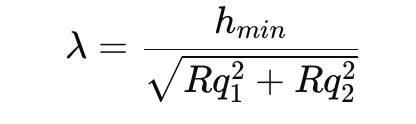
Where:
| Symbol | Meaning |
|---|---|
| (h_{min}) | minimum oil film thickness |
| (Rq_1) | RMS roughness of roller |
| (Rq_2) | RMS roughness of raceway |
| (\lambda) | film thickness ratio |
When (\lambda) is low, the bearing operates in mixed or boundary lubrication. That means asperities touch. Once asperities touch under high load, surface initiated fatigue becomes much more likely.
Low lambda can be caused by:
- oil viscosity too low,
- oil temperature too high,
- speed too low,
- load too high,
- water contamination,
- wrong oil grade,
- oxidized oil,
- poor additive condition,
- surface roughness,
- abrasive wear,
- debris dents.
This is why oil analysis is essential in your case.
15. Why the damaged roller surface looks torn and dark
The dark rough areas can come from several effects:
1. Oxidized fatigue cracks
Once cracks open, oil and oxygen enter. The crack surfaces darken.
2. Contaminated oil trapped inside spalls
Mining gearbox oil often carries fine black debris, oxidized oil, and metal particles.
3. Heat from sliding
If the roller skidded or smeared locally, the surface can become dark and rough.
4. Corrosion-assisted fatigue
Water can create corrosion pits. Those pits become crack origins.
5. Secondary over-rolling
Loose fragments from the first spall are over-rolled and cause further indentation and tearing.
The photos show a very advanced stage. At this point, the original microscopic origin may already be destroyed.
16. Practical root-cause ranking for the attached case
Based on the photos and the mining gearbox context, I would rank the likely causes as follows.
Most likely
1. Surface initiated fatigue from contaminated or degraded oil
The pitting on the adjacent roller and rough strip on the damaged roller strongly support surface distress.
2. Water-assisted corrosion fatigue
Dark pitting and rough etched areas should trigger water testing. Water in gearbox oil is a major cause of corrosion pits and surface-origin fatigue.
3. Hard particle indentation from gear or bearing debris
Gearboxes generate internal debris when gears, bearings, or cages start wearing. Once hard particles enter the bearing contact, surface initiated spalling accelerates.
4. Edge loading or misalignment
If the contact pattern on the raceway is narrow, offset, or concentrated toward one edge, misalignment or housing distortion may have overloaded part of the roller.
Possible
5. Subsurface fatigue from overload
Heavy mining shock load can create premature subsurface spalling. This must be checked by sectioning through the spall.
6. Adhesive wear / smearing before spalling
If the roller had sliding or skewing, adhesive wear could have damaged the surface first, then fatigue followed.
7. White etching crack-related failure
Possible in some large gearbox bearings, especially with water, hydrogen, high stress, or certain lubricant/additive conditions, but it cannot be diagnosed from these photos alone.
17. What evidence you need next
For a professional failure report, collect these items.
Bearing inspection
- inspect all rollers,
- inspect inner ring raceway,
- inspect outer ring raceway,
- mark the load zone,
- look for edge loading,
- check if damage repeats at roller spacing,
- examine cage pockets,
- inspect roller ends and guide ribs,
- check for smearing,
- check for electrical erosion,
- check for corrosion pits,
- document whether spalls are old/dark or fresh/bright.
Oil analysis
Take oil from the gearbox, not only from the drain bottom.
Recommended tests:
- viscosity at 40 °C and 100 °C,
- water content by Karl Fischer,
- particle count,
- ferrous debris / PQ index,
- analytical ferrography,
- elemental analysis,
- TAN,
- oxidation/nitration,
- additive depletion,
- filter debris analysis,
- magnetic plug debris analysis.
Metallurgical inspection
Cut through the damaged roller and examine:
- crack origin,
- crack direction,
- inclusion involvement,
- case depth if case-hardened,
- hardness profile,
- retained austenite if relevant,
- white etching cracks,
- corrosion pits,
- surface microcracks,
- microspalling,
- heat-affected structure.
This is the only reliable way to separate true subsurface fatigue from surface-origin fatigue once the damage is advanced.
18. Corrective actions for mining gearbox bearings
A. Improve oil cleanliness
- upgrade filtration,
- use offline kidney-loop filtration,
- flush after bearing failure,
- inspect filter bypass valves,
- check filter collapse indicators,
- clean magnetic plugs regularly,
- inspect gearbox breathers,
- use proper sealed/desiccant breathers,
- prevent dirt entry during oil top-up.
B. Control water
- test water routinely,
- inspect shaft seals,
- inspect breathers,
- check cooler leaks,
- avoid pressure washing near seals,
- use dehydration or vacuum dehydration if needed,
- monitor oil cloudiness or emulsification.
C. Improve oil film strength
- confirm correct viscosity grade,
- confirm operating oil temperature,
- verify oil level,
- verify oil delivery to bearing,
- check for foaming/aeration,
- inspect oil spray/jet paths if used,
- confirm EP/AW oil meets gearbox OEM requirement,
- avoid mixing incompatible oils.
D. Check alignment and loading
- inspect coupling alignment,
- check soft foot,
- check foundation movement,
- inspect housing bore roundness,
- check bearing fits,
- check shaft runout,
- inspect gear tooth contact pattern,
- check shaft deflection,
- verify bearing internal clearance or preload,
- check whether the gearbox has been overloaded.
E. Improve bearing selection if needed
For repeated failures, consider:
- higher-capacity bearing,
- improved internal geometry,
- optimized roller profile/crowning,
- case-carburized bearing steel for shock duty,
- special heat treatment,
- higher cleanliness steel,
- coating if sliding/smearing is present,
- improved sealing arrangement,
- better lubricant delivery.
F. Monitor the gearbox
- vibration enveloping,
- bearing defect frequency trending,
- oil debris monitoring,
- temperature trending,
- routine oil analysis,
- filter debris inspection,
- borescope inspection during shutdowns.
19. Strong failure-report wording
You can use wording like this:
The removed large gearbox bearing roller shows severe localized rolling contact damage with rough, dark, torn spalling and adjacent surface pitting. The damage morphology is more consistent with advanced surface initiated fatigue than with pure classical subsurface initiated fatigue. The scattered pitting on companion rollers indicates that oil contamination, water ingress, corrosion, hard particle indentation, or degraded lubrication should be considered primary contributors. Because advanced spalling can destroy the original crack origin, final classification requires inspection of the matching raceways, oil analysis, debris analysis, and metallurgical sectioning through the damaged roller. Roller and raceway hardness should be considered comparable; neither component is designed to be sacrificial.
20. Main takeaway
For large mining gearbox bearings:
Subsurface initiated fatigue is a stress/material-origin failure.
Surface initiated fatigue is a lubrication/contamination/surface-origin failure.
Your photos strongly suggest that the surface condition was already compromised before the large spall developed.
The roller is not normally softer or sacrificial. The raceway is not normally sacrificial either. Both are hardened bearing steel components designed to run separated by a clean oil film.
In this case, the most important question is not “roller or raceway, which is harder?”
The better question is:
What destroyed the oil film or damaged the contact surface first?
