How to Use a Feeler Gauge
Practical technical guide for measuring bearing internal clearance
By Khash
A feeler gauge is a simple tool, but in bearing work it is one of the most important precision instruments in the technician’s hand. Used correctly, it tells you whether a bearing has enough internal clearance to operate safely after mounting. Used incorrectly, it can give a false reading and lead to overheating, excessive preload, vibration, skidding, or early bearing failure.
This article focuses on using a feeler gauge to measure the radial internal clearance of spherical roller bearings, especially large industrial bearings mounted in housings, adapter sleeves, withdrawal sleeves, or heavy-duty equipment.
The uploaded procedure this is based on describes measuring spherical roller bearing radial internal clearance using feeler or thickness gauges, with emphasis on cleanliness, correct bearing support, roller alignment, blade position, and repeated verification.
1. What a feeler gauge does
A feeler gauge is a set of thin, accurately ground blades, each with a known thickness. The technician inserts a selected blade into a small gap to determine the size of that gap.
In bearing work, the feeler gauge is commonly used to measure:
- original radial internal clearance before mounting,
- remaining clearance after mounting on a tapered seat or sleeve,
- clearance reduction during drive-up,
- whether the bearing has been over-tightened,
- whether the bearing still has enough residual clearance to run safely.
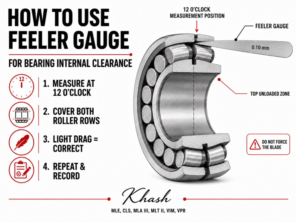
For spherical roller bearings, the measurement is normally taken between the top unloaded roller set and the outer ring raceway.
2. Why internal clearance matters
A rolling bearing must have the correct internal clearance after mounting. This is especially critical for spherical roller bearings because they are often mounted with an interference fit or driven up a tapered sleeve.
When the bearing is pushed onto a taper, the inner ring expands. As the inner ring expands, the internal clearance reduces.
Too much reduction means the bearing becomes too tight.
Too little reduction means the bearing may remain loose.
Both conditions are dangerous.
| Condition | Result |
|---|---|
| Clearance too tight | Heat, preload, lubricant failure, roller/raceway overstress |
| Clearance too loose | Vibration, poor load distribution, roller skidding, fretting |
| Clearance uneven | Misalignment, incorrect seating, distorted readings |
| Clearance not measured | Bearing mounting becomes guesswork |
A feeler gauge does not only measure a gap. It protects the bearing from incorrect installation.
3. Where the clearance is measured
For a spherical roller bearing standing upright, the bearing load from gravity is at the bottom. The top of the bearing is the unloaded zone.
The correct clearance measurement is taken at the 12 o’clock position, between the rollers and the outer ring raceway. The uploaded procedure specifically shows the measurement being taken at the top of the bearing where the rollers are unloaded.
This is important because measuring at the wrong position gives a false result.
| Bearing position | Measurement quality |
|---|---|
| 12 o’clock, unloaded zone | Correct measuring area |
| Bottom loaded zone | Incorrect; rollers are seated by load |
| Side position | Less reliable |
| Misaligned roller rows | False reading |
| Rings not parallel | False reading |
4. Required tools and conditions
Before measuring, prepare the job properly.
You need:
- feeler gauge set,
- clean lint-free gloves,
- clean work surface,
- bearing stand, V-block, or support ring,
- bearing clearance table from the manufacturer,
- clean cloth,
- good lighting,
- recording sheet,
- correct metric or inch units.
The uploaded guide emphasizes using a clean, low-humidity environment, keeping the bearing protected until measurement, and using a V-block or ring to hold the bearing upright.
Cleanliness matters because a small dirt particle can be thicker than the clearance you are trying to measure. Dirt on the gauge, roller, or raceway can create a false high reading.
5. Inspect the feeler gauge first
Before using the gauge, inspect the blades.
Check for:
- bent blades,
- burrs,
- rust,
- dents,
- oil sludge,
- unreadable markings,
- mixed metric and inch blades,
- rough edges,
- blades stuck together.
A damaged feeler blade should not be used on bearing raceways. It can scratch the rolling surface or give an incorrect reading.
For bearing clearance work, a long blade is preferred because it must cover the full length of both roller rows at the same time. The uploaded procedure specifically warns that the blade should be long enough to cover both roller rows simultaneously.
6. Prepare the bearing
Place the bearing upright on a stable stand, V-block, or support ring. The bearing must be steady. It should not rock or tilt during measurement.
Then rotate the inner ring and roller set several full turns. This helps the rollers settle naturally and distributes the internal contact positions.
After that, press down on the inner ring bore and oscillate the inner ring slightly left and right. This seats the inner ring and rollers properly. The uploaded procedure shows this step clearly: press down on the bore while oscillating the inner ring to seat the inner ring and rollers.
This step is often skipped in the field, but it is critical. If the rollers are not seated, the clearance reading can be wrong.
7. Align the two roller rows
A spherical roller bearing has two rows of barrel rollers. Before measuring, those two rows must be aligned so the roller pairs are parallel.
If the roller rows are not aligned, the feeler blade may contact one roller row differently from the other. The result will be a false reading.
Correct condition:
- both roller rows parallel,
- roller pairs aligned,
- rollers sitting squarely,
- no roller row protruding,
- inner and outer ring faces parallel.
The uploaded guide specifically instructs the technician to align the two rows of rollers so the roller pairs are parallel, and also to align the inner and outer ring faces so they are parallel with no protrusion.
8. Pinch the roller rows together
After aligning the rollers, push or pinch the two rows of rollers inward so they are fully seated against the center guide ring and inner ring raceways.
This step removes unwanted roller displacement and makes the clearance measurement more consistent.
The correct condition is:
- both roller rows seated inward,
- rollers contacting the guide ring correctly,
- inner ring centered,
- cage and roller sets not protruding,
- ring faces parallel.
The uploaded procedure describes pinching the two roller rows together so they contact the center guide ring and inner ring raceways before measuring.
9. Select the first blade
Do not start with a thick blade.
Start near the lower end of the specified clearance range. For example, if the expected clearance range is 0.180 to 0.230 mm, start near 0.180 mm and work upward.
The uploaded procedure advises selecting a blade near the bottom of the specified clearance range. It also warns technicians to be careful with metric and inch conversions.
This is a major practical point. Mixing units can cause serious mounting errors.
Example:
| Metric | Inch |
|---|---|
| 0.10 mm | 0.0039 in |
| 0.20 mm | 0.0079 in |
| 0.30 mm | 0.0118 in |
| 0.40 mm | 0.0157 in |
Do not estimate conversion mentally during a critical bearing installation. Use a verified chart.
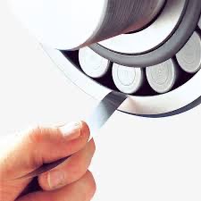
10. Insert the feeler blade correctly
Insert the blade between one pair of rollers and the outer ring raceway at the top of the bearing.
The blade should enter:
- at the 12 o’clock unloaded zone,
- between the roller and outer ring,
- close to one side of the rollers,
- flat against the contact area,
- without forcing,
- without scratching the raceway.
The uploaded procedure shows the blade being slid between the roller and outer raceway close to one side of the rollers.
Do not insert the blade at an angle. Do not push it between misaligned rollers. Do not force it into the loaded zone.
11. Make sure the blade covers both roller rows
This is one of the most important details.
The blade must cover the full length of both roller rows at the same time. If the blade only touches one row, the reading is not a true radial internal clearance reading for the bearing assembly.
Correct:
- blade spans both rows,
- blade sits flat,
- both roller rows contact the blade,
- blade is centered across the roller pair.
Incorrect:
- blade contacts only one row,
- blade is too short,
- blade is angled,
- blade contacts the cage,
- blade rides on an edge.
The uploaded document emphasizes that the blade must cover the full length of both roller rows at the same time.
12. Roll the roller onto the blade
After placing the blade, rotate the inner ring slightly. This moves the roller up onto the center of the blade.
The purpose is to seat the roller properly on the feeler blade and create a consistent measuring condition.
But do not rotate too far.
The uploaded procedure says to rotate the inner ring slightly to drive the roller onto the center of the blade, and then warns not to roll past the center of the pinched blade.
Correct position:
- blade is on top of the roller,
- roller is centered on the blade,
- blade is not off to one side,
- blade is not trapped beyond the centerline.
Incorrect position:
- roller has passed over the blade,
- blade is off-center,
- blade is pinched at an angle,
- blade is bent or distorted.
13. Pull the blade and feel the drag
Once the blade is correctly positioned, hold the bearing firmly and pull the blade toward you.
The correct feel is a smooth, light drag.
The blade should not fall out freely, and it should not require heavy force. A feeler gauge reading is partly mechanical and partly tactile. The technician must develop a consistent “feel.”
| Blade feel | Meaning |
|---|---|
| Falls out freely | Blade is too thin |
| Smooth light drag | Correct candidate thickness |
| Requires hard pulling | Blade may be too thick |
| Blade bends | Too thick or misaligned |
| Blade scratches | Wrong angle, dirt, or damaged blade |
| Cannot move | Too thick or roller passed too far over blade |
The uploaded guide instructs the technician to pull the blade outward once it is aligned and properly seated, while holding the bearing firmly in place.
14. Increase blade thickness progressively
After the first blade, repeat the same process using progressively thicker blades.
The goal is to find the largest blade that can still be pulled through properly.
Do not jump from a thin blade to a much thicker blade. Increase gradually.
The uploaded procedure states that the technician should repeat the process with progressively larger gauges until the gauge can no longer be pulled easily through the bearing. The largest blade that can be pulled through is the measured radial internal clearance.
This is the key measurement rule:
The largest blade that pulls through with correct feel equals the measured internal radial clearance.
15. Repeat the measurement
One reading is not enough.
Repeat the measurement at two or three positions around the bearing to verify consistency. The uploaded procedure also instructs repeating the process at two or three different bearing positions to verify the result.
Record each reading.
Example format:
| Position | Reading |
|---|---|
| Position 1 | 0.220 mm |
| Position 2 | 0.225 mm |
| Position 3 | 0.220 mm |
| Final recorded clearance | 0.220–0.225 mm |
If the readings vary significantly, investigate before proceeding.
Possible causes of variation:
- rings not parallel,
- rollers not aligned,
- bearing not seated,
- dirty gauge blade,
- damaged roller,
- damaged raceway,
- cage interference,
- bearing tilted on stand,
- uneven handling,
- wrong measuring position.
16. How to use a feeler gauge during mounting
For tapered-bore spherical roller bearings, the feeler gauge is commonly used before and during mounting.
The general method is:
- Measure original internal clearance before mounting.
- Mount the bearing on the taper or adapter sleeve.
- Drive the bearing up gradually.
- Recheck clearance.
- Continue until the specified clearance reduction is achieved.
- Confirm that final residual clearance remains within the manufacturer’s minimum limit.
Example concept:
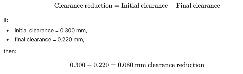
This reduction must be compared with the bearing manufacturer’s mounting table.
Never use random drive-up force. Never mount a large spherical roller bearing by “feel” only.
17. Common mistakes
Mistake 1: Measuring before seating the rollers
If the rollers are not settled, the reading may be too high or inconsistent.
Mistake 2: Measuring at the bottom
The bottom rollers are loaded by the weight of the bearing. The correct area is the top unloaded zone.
Mistake 3: Using a blade that is too short
The blade must cover both roller rows. A short blade gives a false reading.
Mistake 4: Rolling past the blade center
If the roller passes too far over the blade, the blade becomes off-center and the reading is wrong.
Mistake 5: Forcing the blade
A forced blade can scratch the raceway, bend the blade, and give a false high reading.
Mistake 6: Ignoring unit conversion
Metric and inch errors are common and dangerous.
Mistake 7: Not repeating the reading
A single reading does not confirm bearing condition.
Mistake 8: Measuring a dirty bearing
Dirt can be thicker than the clearance being measured.
Mistake 9: Measuring with misaligned rings
If the inner and outer rings are not parallel, the reading is not reliable.
Mistake 10: Recording only “OK”
Record the actual measured values, not just a pass/fail judgment.
18. Troubleshooting inconsistent readings
| Problem | Likely cause | Correction |
|---|---|---|
| Reading changes every time | Rollers not seated | Rotate, oscillate, and reseat bearing |
| One position reads much tighter | Ring tilt or damage | Check alignment and inspect surfaces |
| Blade drags on one roller row only | Blade too short or angled | Use longer blade and align correctly |
| Blade scratches | Dirt, burr, or wrong angle | Clean gauge and bearing, inspect blade |
| Thick blade fits too easily | Wrong position or unloaded roller not seated | Re-seat rollers and remeasure |
| Cannot insert expected blade | Bearing too tight or misaligned | Stop and check mounting |
| Clearance reduced too much | Excessive drive-up | Consult manufacturer before continuing |
| Clearance not reducing | Sleeve not moving, fit issue, wrong setup | Check mounting method |
19. Special notes for large bearings
Large bearings require more discipline because the parts are heavy and clearances are small relative to bearing size.
For large bearings:
- use a stable stand,
- use two technicians if needed,
- avoid tilting the bearing,
- use long feeler blades,
- keep hands clear of pinch points,
- do not spin the bearing aggressively,
- support the bearing securely,
- record readings immediately,
- verify with manufacturer tables,
- use hydraulic nut or drive-up method where specified.
Large spherical roller bearings often fail early because of incorrect residual clearance. The feeler gauge is the technician’s last confirmation before the bearing enters service.
20. Safety notes
A feeler gauge measurement looks simple, but large bearings can pinch fingers and damage surfaces.
Use:
- clean gloves,
- stable support,
- controlled handling,
- lifting aids for large bearings,
- no loose sleeves or unstable stands,
- no hammering near the measurement area,
- no forcing of gauge blades.
Also protect the bearing. A bearing raceway is a precision surface, not a workbench.
21. Practical field checklist
Before measurement:
- Bearing clean and protected.
- Correct clearance table available.
- Correct unit system confirmed.
- Feeler blades clean and undamaged.
- Bearing supported upright.
- Inner ring and roller set rotated.
- Rollers seated.
- Roller rows aligned.
- Ring faces parallel.
- Measurement taken at top unloaded zone.
During measurement:
- Start near bottom of specified range.
- Insert blade between top rollers and outer ring.
- Blade covers both roller rows.
- Roller is centered on blade.
- Blade pulls with light drag.
- Increase blade thickness gradually.
- Do not force.
- Do not roll past center.
After measurement:
- Record largest blade that pulls correctly.
- Repeat at two or three positions.
- Compare with specification.
- Record initial and final clearance.
- Confirm residual clearance before release.
22. Example report wording
Radial internal clearance was measured using calibrated feeler gauges. The bearing was positioned upright on a stable support, the inner ring and roller set were rotated and seated, both roller rows were aligned, and the inner and outer ring faces were confirmed parallel. Measurement was taken at the 12 o’clock unloaded zone between the roller pair and outer ring raceway. The feeler blade covered both roller rows and was pulled through after the roller was centered on the blade. The largest blade that could be pulled through with light drag was recorded as the radial internal clearance. Measurements were repeated at multiple positions for verification.
23. Main takeaway
A feeler gauge is only accurate when the bearing is prepared correctly.
The most important points are:
Clean bearing. Seated rollers. Aligned roller rows. Measurement at 12 o’clock. Blade across both roller rows. Roller centered on blade. Largest blade pulled with correct feel equals clearance.
Used correctly, the feeler gauge prevents one of the most common bearing installation failures: incorrect internal clearance.
Khash
MLE, CLS, MLA III, MLT II, VIM, VPR
