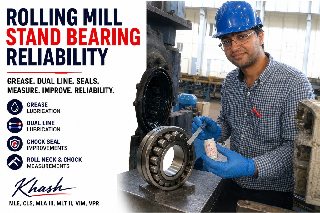
Rolling Mill Stand Bearing Reliability
From roughing to intermediate to finishing stands — combining grease lubrication, dual-line systems, chock seals, roll neck measurement, and chock measurement into one reliability program
By Khash
Rolling mill stand bearing reliability is not solved by changing the bearing brand, increasing grease quantity, or repairing one chock after failure. In roughing, intermediate, and finishing stands, the bearing works inside a complete mechanical and lubrication system:
bearing + grease + dual-line lubrication system + chock seal + roll neck + chock bore + cooling water + scale + mill load + maintenance discipline.
When one of these elements is weak, the bearing becomes the final victim.
The approach I use is simple in concept but strict in execution:
Do not treat stand bearing failures as isolated bearing failures. Treat them as system failures involving lubrication delivery, contamination exclusion, mechanical fits, and measurement control.
1. Why rolling mill stand bearings are severe-duty bearings
Rolling mill stand bearings work in one of the most aggressive bearing environments in industry. They carry high rolling forces, shock loads, vibration, water, scale, heat, contamination, and frequent roll changes.
The work roll bearing arrangement is constrained by roll neck diameter and minimum roll diameter, so the bearing must provide maximum load capacity inside limited available space. NSK describes four-row tapered roller bearings for roll neck applications as being designed to achieve as much load rating as possible within those dimensional limits.
Typical rolling mill bearing stressors include:
| Stressor | Effect on bearing |
|---|---|
| Rolling load | high Hertzian stress on rollers and raceways |
| Shock load | surface distress, cage damage, raceway spalling |
| Cooling water | grease washout, corrosion, hydrogen-assisted damage |
| Mill scale | abrasive contamination and seal wear |
| Roll neck wear | poor fit, creep, fretting, heat |
| Chock bore distortion | edge loading and poor load distribution |
| Overgreasing | heat, churning, seal damage |
| Undergreasing | smearing, starvation, wear |
| Blocked lubrication lines | dry bearing despite “system running” |
| Poor sealing | water and scale enter faster than grease can protect |
| Incorrect chock handling | seal damage and contamination during assembly |
SKF states that four-row cylindrical roller bearings used in rolling mill stands must be properly lubricated and protected from contamination, and that periodic maintenance inspections are essential.
That one sentence captures the entire reliability problem: lubrication and contamination control must be managed together.
2. Bearing demands by stand area
Roughing stands
Roughing stands see the most violent mechanical conditions. The incoming billet, slab, bloom, or bar is larger, hotter, and less dimensionally stable. Loads are high. Shock is high. Scale is heavy. Cooling water and descaling water are aggressive.
Main roughing stand bearing threats
| Threat | Typical result |
|---|---|
| High rolling load | subsurface fatigue, raceway spalling |
| Shock load | cage fracture, roller edge distress |
| Heavy scale | seal wear, abrasive contamination |
| Water ingress | rust, grease washout, pitting |
| Roll neck wear | cone creep, fretting, poor seating |
| Chock bore wear | misalignment and edge loading |
| Blocked grease line | sudden starvation |
Reliability focus for roughing stands
For roughing stands, the program must prioritize:
- robust grease film strength,
- high water resistance,
- effective purge at seals,
- strong dual-line delivery verification,
- chock seal protection,
- roll neck dimensional control,
- chock bore condition,
- heavy-duty inspection after every roll change.
In roughing stands, the question is not only “is grease present?”
The better question is:
Is clean grease reaching the loaded bearing contact while contaminated grease, water, and scale are being pushed away from the seal zone?
Intermediate stands
Intermediate stands are the transition zone. Loads are still significant, but speeds increase. The product is smaller, rolling becomes more continuous, and bearing failures become more sensitive to lubrication balance and alignment.
Main intermediate stand threats
| Threat | Typical result |
|---|---|
| Moderate-to-high speed | heat if overgreased |
| Residual scale and water | abrasive wear and corrosion |
| Chock interchange | incorrect chock/roll matching |
| Lubrication imbalance | some points starve while others purge |
| Roll neck wear | progressive looseness and fretting |
| Seal lip wear | water bypass into bearing cavity |
Reliability focus for intermediate stands
Intermediate stands require controlled lubrication, not aggressive lubrication. Too much grease creates heat and churning. Too little grease causes starvation and smearing.
The focus should be:
- calibrated injector output,
- correct grease quantity by stand,
- inspection of dual-line indicator pins,
- seal purge control,
- chock bore measurement,
- roll neck taper/diameter verification,
- stand-side failure tracking: drive side vs operator side.
Intermediate stand reliability improves when the mill stops treating all stands as the same lubrication problem.
Finishing stands
Finishing stands are precision-sensitive. Speeds are higher, roll sizes are smaller, and the tolerance for bearing heat, vibration, roll eccentricity, seal drag, and contamination is lower.
Main finishing stand threats
| Threat | Typical result |
|---|---|
| Higher speed | grease churning, temperature rise |
| Small roll diameter | limited bearing envelope |
| High cooling water exposure | seal failure and grease washout |
| Tight product tolerance | vibration and runout sensitivity |
| Frequent roll changes | handling damage and contamination |
| Overgreasing | heat, seal blowout, grease leakage |
Reliability focus for finishing stands
For finishing stands, the program must prioritize:
- controlled grease volume,
- correct grease consistency and pumpability,
- seal lip condition,
- clean chock assembly,
- precise chock and roll neck measurements,
- temperature trending,
- vibration trending,
- prevention of overgreasing.
The finishing stand rule is:
Precision stands need precision lubrication. More grease is not precision. Correct grease volume is precision.
3. Bearing types used in rolling stands
Rolling mill stand bearings commonly use multi-row roller bearing arrangements because of the high load and limited radial space.
Four-row tapered roller bearings
Four-row tapered roller bearings are widely used in work roll applications because they can carry combined radial and axial loads. SKF describes four-row tapered roller bearings as suitable for combined radial and axial loads at low to moderate speeds and used almost exclusively in work roll applications. (SKF)
Their strengths:
- high radial load capacity,
- axial load capacity in both directions,
- compact roll neck arrangement,
- suitable for heavy stand duty,
- good for work roll chocks.
Their risks:
- sensitive to contamination,
- sensitive to mounting and cup clamping,
- sensitive to chock and roll neck condition,
- vulnerable to seal damage,
- needs correct lubricant and purge.
Four-row cylindrical roller bearings
Four-row cylindrical roller bearings are often used where very high radial load capacity is required. SKF identifies these bearings as a solution for high radial and axial forces in roughing and intermediate stands and highlights benefits such as high load-carrying capacity, longer service life, easier maintenance, and improved sealing.
Their strengths:
- very high radial capacity,
- good speed capability,
- separable design,
- easier inspection in some designs,
- useful for roughing and intermediate stand duty.
Their risks:
- axial load must be handled by the correct arrangement,
- edge loading if chock or roll neck geometry is poor,
- lubrication starvation under high load,
- contamination from water and scale.
Sealed roll neck bearings
Sealed roll neck bearings are used to improve contamination control and reduce grease loss. Timken notes that contaminants and water ingress reduce bearing life, while excessive grease loss increases maintenance cost and can cause strip staining; improved main seal design is intended to address these concerns.
Schaeffler also notes that sealed tapered roller bearings with integrated seals use high-grade rolling bearing grease that does not escape from the bearing, reducing grease consumption, and that improved cleanliness in the lubricating gaps generally gives longer life than unsealed bearings. (Schaeffler)
This is important for steel plants because many mill failures are not pure fatigue failures. They are contamination-assisted failures.
4. The Khash reliability model
The reliability model has four technical pillars:
- Grease lubrication expertise
- Dual-line lubrication system expertise
- Chock seal improvement
- Roll neck and chock measurement control
The power of the program is not in any one pillar alone. The power is in combining all four.
A steel plant may already have good grease, but bad seals.
Or good seals, but blocked dual-line injectors.
Or good lubrication, but worn roll necks.
Or good roll necks, but distorted chocks.
The bearing only survives when all four pillars are controlled together.
5. Pillar 1 — Grease lubrication expertise
5.1 Grease must be selected for stand duty, not for convenience
Rolling mill stand grease must survive:
- high load,
- shock,
- water,
- scale,
- vibration,
- intermittent operation,
- high temperature near hot product,
- low-speed heavy-load rolling,
- higher-speed finishing operation,
- long pipe runs in lubrication systems.
Key grease properties:
| Property | Why it matters |
|---|---|
| base oil viscosity | supports oil film under load |
| NLGI grade | controls pumpability and retention |
| thickener type | affects water resistance and compatibility |
| EP/AW additives | protects under high load and shock |
| mechanical stability | prevents softening under shear |
| water washout resistance | critical in wet stands |
| corrosion protection | protects raceways and roll necks |
| pumpability | essential for long dual-line systems |
| oxidation resistance | extends service life |
| compatibility | prevents hardening/softening when mixed |
A grease may be excellent in a bearing but poor in a dual-line system if it cannot pump through long lines. Another grease may pump well but wash out too easily in wet stands. The correct selection must satisfy both the bearing contact and the delivery system.
5.2 The grease has two jobs
In rolling mill stands, grease does two different jobs:
- Lubricate the rolling contact
- Act as a contamination barrier
The grease inside the bearing must form a film between rollers and raceways. The grease near the seal must help purge water, scale, and coolant away from the chock.
These two jobs must be separated mentally.
| Grease zone | Main function |
|---|---|
| Bearing internal grease | film formation and fatigue protection |
| Seal cavity grease | contamination purge and water blocking |
| Chock cavity grease | barrier and corrosion protection |
| External purge grease | pushes dirt and water outward |
A common mistake is filling the whole chock area aggressively and assuming the bearing is protected. That may only create churned grease, seal pressure, or leakage. The goal is not “a lot of grease.” The goal is correct grease in the correct zone.
5.3 Under-lubrication failure pattern
When grease does not reach the bearing, typical findings include:
- dry roller surfaces,
- heat discoloration,
- smearing,
- cage wear,
- roller end distress,
- rapid vibration increase,
- localized spalling,
- dark overheated grease,
- high bearing temperature.
Possible causes:
- blocked injector,
- broken grease line,
- incorrect dual-line changeover,
- grease too stiff,
- air in lines,
- wrong connection point,
- old hardened grease in chock,
- technician closed a valve,
- point omitted during rebuild.
5.4 Over-lubrication failure pattern
Overgreasing can be as damaging as undergreasing.
Typical findings:
- high temperature after lubrication,
- grease leakage from seals,
- blown seal lips,
- grease churning,
- excessive motor load or drive power,
- grease entering unwanted cavities,
- thick black churned grease,
- product contamination,
- strip staining in flat mills.
Possible causes:
- injector output too high,
- same grease volume used for all stands,
- dual-line system set by guesswork,
- blocked relief path,
- wrong grease consistency,
- manual greasing added on top of automatic lubrication,
- technicians “assist” the system with grease guns.
The program rule is:
If a dual-line system is installed, manual greasing must be controlled. Manual top-up without diagnosis destroys lubrication discipline.
6. Pillar 2 — Dual-line lubrication system expertise
6.1 What a dual-line system does
A dual-line grease system uses two main lines. One line is pressurized while the other is relieved. Metering valves shift under pressure and deliver measured grease volumes to lubrication points. Then the system reverses and pressurizes the opposite line.
Dual-line systems are suitable for steel plants because they can feed many points over long distances and can work in harsh environments when designed and maintained correctly.
But the system must prove grease delivery. Pressure at the pump is not enough.
Pump pressure proves the pump is working. It does not prove each chock bearing received grease.
6.2 Why dual-line systems fail in rolling mills
Common failures include:
| Failure | Effect |
|---|---|
| blocked injector | one bearing starves |
| line rupture | grease lost before reaching chock |
| air trapped in line | delayed or inconsistent delivery |
| wrong injector size | overgrease or undergrease |
| no changeover pressure | system stalls |
| grease too stiff | high pressure, poor delivery |
| water inside line | corrosion and blockage |
| damaged indicator pin | false confidence |
| same setting for all stands | wrong lubrication by duty |
| chock port blocked | grease reaches fitting but not bearing |
| no feedback route | failures remain hidden |
The biggest dual-line mistake in steel plants is believing the system is automatic, therefore it is reliable.
A dual-line system is reliable only when it is:
- pressure-tested,
- bled,
- calibrated,
- mapped,
- inspected,
- alarmed,
- sampled,
- and verified at the bearing point.
6.3 What Khash checks in a dual-line audit
A proper dual-line lubrication audit includes:
Pump station
- reservoir cleanliness,
- grease compatibility,
- pump output,
- pump pressure,
- pressure relief valve,
- changeover valve,
- filter condition,
- low-level alarm,
- moisture entry,
- contamination in reservoir,
- correct grease identification.
Main lines
- line routing,
- pipe damage,
- supports,
- heat exposure,
- corrosion,
- dead legs,
- old grease accumulation,
- pressure drop,
- leaks,
- cross-connections,
- blocked sections.
Metering valves / injectors
- correct size,
- correct location,
- visible indicator movement,
- no stuck pistons,
- no bypassing,
- correct outlet mapping,
- correct cycle count,
- matching stand duty.
Chock connections
- correct port,
- open grease path,
- no wrong fittings,
- no plugged passages,
- no crushed hoses,
- no mixed grease,
- no manual bypass.
Control system
- pressure switch locations,
- cycle time,
- alarm logic,
- changeover pressure,
- blocked-line alarm,
- low-level alarm,
- run permissive,
- event history,
- maintenance response.
6.4 Stand-specific lubrication logic
A strong program does not feed all stands equally.
| Stand area | Lubrication approach |
|---|---|
| Roughing | higher purge demand, robust contamination defense, shock-load grease |
| Intermediate | balanced grease delivery, careful seal purge, injector verification |
| Finishing | controlled low-volume delivery, avoid churning, high inspection discipline |
The dual-line system must reflect actual bearing duty.
Roughing stands may need more contamination purge.
Finishing stands may need less grease but higher precision.
Intermediate stands need balance.
The system must be engineered by stand duty, not by convenience.
7. Pillar 3 — Chock seal improvements
7.1 The chock seal is the bearing’s first defense
A rolling mill bearing rarely fails because the grease was missing from the plant warehouse. It fails because clean grease did not stay clean inside the chock.
The chock seal must stop:
- water,
- scale,
- coolant,
- dirt,
- steam,
- abrasive fines,
- oxidized grease,
- external contamination.
If the seal fails, the bearing becomes a grinding machine.
Timken notes that contamination and water ingress can reduce bearing life in roll neck applications.
7.2 Common chock seal failure modes
| Seal problem | Result |
|---|---|
| worn seal lip | water enters bearing cavity |
| hardened elastomer | loss of contact and leakage |
| damaged spring | reduced lip pressure |
| cut lip during assembly | immediate contamination path |
| worn seal riding surface | leakage even with new seal |
| incorrect seal orientation | grease escapes, water enters |
| poor axial location | lip runs outside correct track |
| excessive shaft/chock runout | lip pumping and wear |
| blocked drain | water trapped at seal |
| no purge grease | scale packs against lip |
| wrong seal material | heat or chemical attack |
A seal is not improved only by changing the seal. The riding surface, axial location, chock cover, purge path, and assembly practice must be improved together.
7.3 Seal improvement actions
A proper chock seal improvement program includes:
- inspection of seal groove dimensions,
- inspection of seal riding surface,
- replacement of worn sleeves or collars,
- removal of burrs and sharp edges,
- correct seal material selection,
- correct seal orientation,
- controlled seal installation tools,
- grease purge cavity design,
- water drain improvement,
- labyrinth clearance check,
- cover flatness check,
- chock face sealing,
- contamination shield improvement.
Timken’s TQO manual emphasizes inspection of the roll neck and seal riding surfaces, removal of burrs or sharp edges, and coating the neck and seal riding surface with the same lubricant as the bearing to combat scuffing and ease installation.
This is a very practical point. A new seal on a damaged seal riding surface is not a repair. It is only a temporary delay.
8. Pillar 4 — Roll neck and chock measurements
8.1 Why measurement control is the missing link
Many rolling mill bearing failures are blamed on grease, but the true root cause is often mechanical geometry:
- worn roll neck,
- oval chock bore,
- bell-mouthed chock seat,
- distorted cover,
- poor shoulder contact,
- axial clamping error,
- seal riding surface wear,
- fretting,
- roll neck taper error,
- chock bore out-of-round.
Timken’s engineering manual states that chock bores, roll neck seats, and shoulders are important contact surfaces subject to wear and distortion, and that these surfaces must be maintained for optimal bearing performance.
This is why the reliability program must include measurements, not only lubrication.
8.2 Roll neck measurements
Roll neck inspection should include:
| Measurement | Why it matters |
|---|---|
| neck diameter | controls bearing fit |
| neck taper | prevents uneven load and creep |
| ovality | affects load distribution |
| cylindricity | affects contact pattern |
| shoulder squareness | affects axial seating |
| fillet radius | prevents stress and seating problems |
| surface roughness | affects fit and fretting |
| seal riding surface diameter | controls seal contact |
| seal riding surface wear | determines leakage risk |
| runout | affects bearing and seal life |
| nicks and gouges | cause assembly damage and fretting |
Timken’s TQO manual states that before mounting the chock and bearing assembly, the roll neck should be cleaned, checked for size, and inspected, and that raised nicks or gouges should be stoned or filed down before reassembly.
Roll neck measurement must be recorded. It should not depend on memory or visual inspection only.
8.3 Chock measurements
Chock inspection should include:
| Measurement | Why it matters |
|---|---|
| chock bore diameter | controls cup/ring seating |
| chock bore ovality | causes uneven bearing support |
| bore taper | causes edge loading |
| bore bellmouth | reduces support at one end |
| shoulder squareness | affects axial clamping |
| cover fit | affects seal and bearing location |
| keeper plate condition | affects chock stability |
| wear plate condition | affects stand alignment |
| seal groove condition | affects contamination control |
| drain path condition | prevents water retention |
| grease passage condition | ensures lubrication delivery |
A bearing can be perfect. The grease can be perfect. The dual-line system can be working. But if the chock bore is distorted, the bearing load is no longer distributed correctly.
8.4 Measurement discipline
Measurement discipline matters because small errors become large bearing stresses.
A useful principle from the uploaded feeler-gauge procedure is that bearing measurement work should be done in clean conditions, with the bearing properly seated, aligned, and checked repeatedly rather than judged by a single casual reading. That same discipline applies to roll neck and chock measurement: clean the part, seat it correctly, use the correct tool, measure at several clock positions, record the numbers, and verify repeatability.
9. How the four pillars work together
The full program works like this:
Step 1: Failure mapping by stand
Each failure is tagged by:
- mill area,
- stand number,
- drive side or operator side,
- top or bottom roll,
- bearing type,
- chock number,
- roll number,
- grease batch,
- lubrication line,
- seal design,
- failure mode,
- operating hours,
- tonnage rolled,
- product size,
- water exposure,
- temperature,
- vibration.
Without this mapping, every failure looks random.
Step 2: Bearing damage classification
Each failed bearing is classified:
| Damage | Likely system issue |
|---|---|
| rust / brown grease | water ingress |
| abrasive scoring | scale/dust contamination |
| smearing | starvation or sliding |
| cage wear | misalignment, starvation, vibration |
| edge spalling | chock or roll neck geometry |
| uniform overheating | overgreasing or preload |
| one-row damage | misalignment or axial loading issue |
| repeated same-side failure | stand geometry or lubrication mapping |
| seal-side failure | seal or purge problem |
| inner ring fretting | roll neck fit or creep |
The bearing tells a story. The job is to connect the damage to the system.
Step 3: Grease and system audit
For each stand group:
- identify current grease,
- check grease compatibility,
- sample used grease,
- inspect water content,
- check metallic debris,
- inspect consistency change,
- verify pumpability,
- verify dual-line injector outputs,
- compare actual grease delivery to required delivery,
- check manual greasing habits,
- remove uncontrolled top-up practice.
Step 4: Chock seal audit
Each chock is inspected for:
- seal lip wear,
- seal orientation,
- seal material,
- seal groove condition,
- seal riding surface,
- purge path,
- drain path,
- water path,
- cover fit,
- seal installation damage.
Then chocks are ranked:
| Condition | Action |
|---|---|
| good | reuse with standard inspection |
| worn but serviceable | repair next shutdown |
| high-risk | rebuild before next campaign |
| failed | remove from service |
Step 5: Roll neck and chock measurement program
A measurement sheet is created for each roll and chock.
The sheet should include:
- roll ID,
- chock ID,
- bearing ID,
- neck measurements at multiple clock positions,
- chock bore measurements at multiple depths,
- seal land dimensions,
- shoulder runout,
- surface condition,
- repair notes,
- acceptance/rejection status.
Timken specifically recommends keeping records of each roll neck inspection and measurement and making repairs when necessary.
Step 6: Corrective action by root cause
Examples:
| Root cause | Corrective action |
|---|---|
| blocked injector | clean/replace injector, verify flow |
| wrong grease | convert with purge and compatibility control |
| water ingress | improve seal, drain, purge, water shielding |
| roll neck wear | grind, sleeve, repair, or scrap |
| chock bore distortion | machine/recondition chock |
| overgreasing | reduce injector volume and stop manual top-up |
| seal damage during assembly | introduce seal installation tooling |
| recurring drive-side failures | inspect alignment, load, chock fit, lube mapping |
| finishing stand heat | reduce grease quantity, check seal drag |
| roughing stand contamination | increase seal purge and improve seal package |
10. Practical roughing-to-finishing reliability matrix
| Area | Main failure driver | Lubrication focus | Seal focus | Measurement focus |
|---|---|---|---|---|
| Roughing | shock, load, scale, water | EP grease, strong purge, verified delivery | robust seals, scale exclusion, drain paths | roll neck wear, chock bore distortion |
| Intermediate | mixed load/speed, water, alignment | balanced injector output, no starvation | seal lip wear, purge control | chock bore, seal land, stand-side trends |
| Finishing | speed, heat, precision | controlled grease volume, avoid churning | low-drag but effective sealing | runout, chock precision, seal alignment |
11. The most important practical checks
Before roll/chock assembly
- clean chock and bearing area,
- inspect bearing,
- inspect grease condition,
- inspect seal lips,
- inspect seal riding surfaces,
- measure roll neck,
- measure chock bore,
- remove burrs,
- confirm grease passages,
- confirm correct bearing orientation,
- protect bearing from contamination.
During assembly
- use correct lifting and handling,
- align chock square to roll neck,
- avoid seal damage,
- lubricate seal riding surfaces,
- avoid forcing over burrs,
- confirm axial clamping,
- confirm covers and gaskets,
- avoid dirty hands/tools contacting bearing.
Timken’s engineering manual emphasizes careful alignment of the chock and bearing assembly with the roll neck, ensuring the chock is square and cone bores are centered, and taking care to avoid seal damage during chock assembly installation.
After assembly
- confirm grease purge path,
- check dual-line point connection,
- cycle lubrication system,
- verify injector movement,
- check for leakage,
- record chock and roll ID,
- monitor temperature after startup,
- trend vibration and grease condition.
12. Reliability KPIs
A serious steel plant reliability program should track:
| KPI | Purpose |
|---|---|
| bearing life by stand | identifies weak stand areas |
| bearing consumption per ton | normalizes production volume |
| chock failure rate | detects mechanical/support issues |
| seal replacement frequency | detects contamination defense weakness |
| grease consumption per stand | detects over/under-lubrication |
| injector failure count | measures dual-line health |
| water-contaminated grease samples | measures seal performance |
| roll neck rejection rate | measures roll maintenance quality |
| chock bore rework rate | measures chock condition |
| unplanned chock changes | reliability outcome |
| drive-side vs operator-side failures | detects asymmetric issues |
| repeat failures by chock ID | exposes bad chocks returning to service |
The most valuable KPI is not simply “number of bearings changed.”
It is:
Bearing life by stand, side, chock ID, and root cause.
13. What this program changes in the plant
Before the program:
- failures are blamed on bearings,
- grease is increased after every failure,
- chock seals are replaced but not redesigned,
- dual-line systems are assumed to work,
- roll necks are visually inspected only,
- chock bores are rarely measured,
- failures repeat on the same stands.
After the program:
- failures are classified by mechanism,
- grease quantity is calculated,
- injector outputs are verified,
- seal purge is controlled,
- roll necks are measured and recorded,
- chocks are measured and ranked,
- bad chocks are removed from circulation,
- contamination entry paths are corrected,
- lubrication becomes stand-specific,
- bearing life is tracked by tonnage and stand.
14. Strong technical statement
The reliability philosophy can be summarized like this:
Rolling mill stand bearing life is controlled by the cleanliness and stability of the rolling contact. Grease selection alone cannot protect the bearing if the dual-line system does not deliver, if the chock seal admits water and scale, if the roll neck is worn, or if the chock bore is distorted. The correct reliability program combines lubrication engineering, delivery-system verification, seal improvement, and dimensional control of the roll neck and chock.
15. Main takeaway
Roughing, intermediate, and finishing stand bearings fail for different reasons, but the solution must be integrated.
Roughing stands need strength and contamination defense.
Intermediate stands need balance and delivery control.
Finishing stands need precision and controlled lubrication.
Khash’s rolling mill bearing reliability program is built around one practical truth:
The bearing is not the program. The system around the bearing is the program.
The winning formula is:
correct grease + verified dual-line delivery + improved chock sealing + measured roll necks + measured chocks + disciplined failure tracking.
Khash
MLE, CLS, MLA III, MLT II, VIM, VPR
 Rolling Bearing Reliability